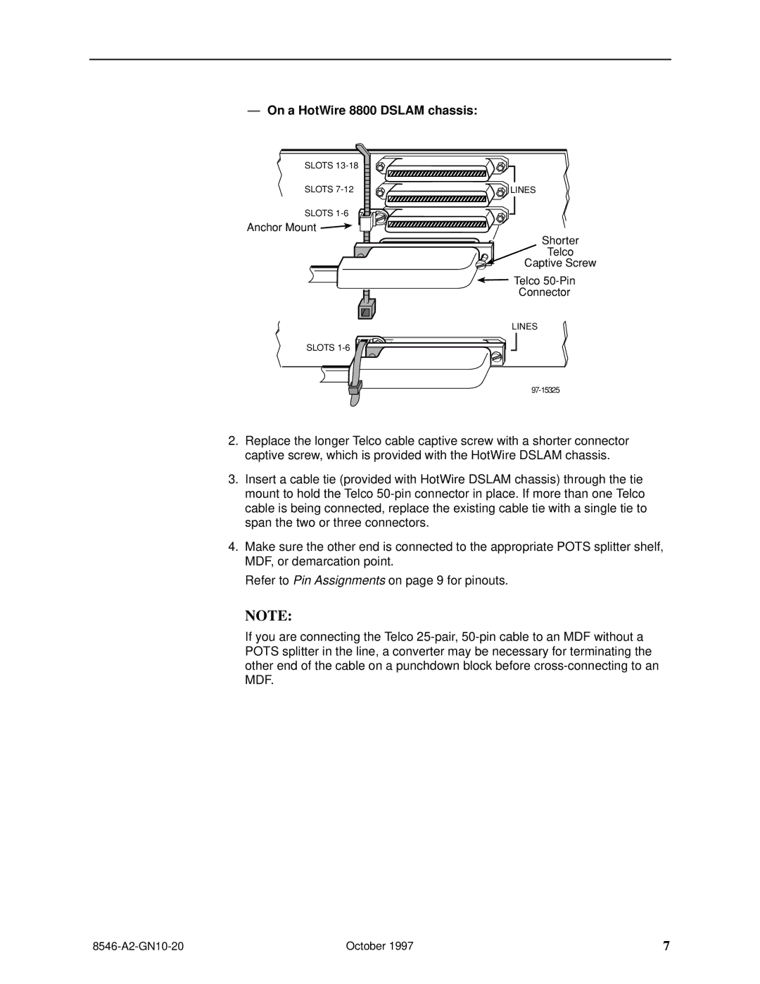
ÐOn a HotWire 8800 DSLAM chassis:
SLOTS |
|
SLOTS | LINES |
SLOTS
Anchor Mount ![]()
Shorter
Telco
Captive Screw
![]() Telco
Telco
Connector
LINES
SLOTS ![]()
![]()
![]()
![]()
![]()
![]()
2.Replace the longer Telco cable captive screw with a shorter connector captive screw, which is provided with the HotWire DSLAM chassis.
3.Insert a cable tie (provided with HotWire DSLAM chassis) through the tie mount to hold the Telco
4.Make sure the other end is connected to the appropriate POTS splitter shelf, MDF, or demarcation point.
Refer to Pin Assignments on page 9 for pinouts.
NOTE:
If you are connecting the Telco
| October 1997 | 7 |