Training & Maintenance Manual |
Installation & Setup Instructions
Setup
Below are the step by step setup procedures for properly setting the flow control and feedback sensor.
How to Set the Flow Control Properly
Begin by turning the flow control clockwise until it stops. If this is done properly, then the weld stroke should move extremely slow or not at all.
Note: As stated in the Installation procedure, the
Slowly (1/4 to 1/2 turn at a time) begin to open the flow control by turning counterclockwise. The weld tips should now close upon actuation of the valves. At this point, you should begin to hear a second exhaust coming from the weld unit once the weld tips have made contact. This second exhaust is the air from the front side of the cylinder bypassing the flow control. As you continue to speed up the weld stroke by turning the flow control, the delay between the tips closing and the second exhaust will get shorter. Also, check the feedback sensor while this is occurring. The indicator light from the sensor should illuminate when you hear the second exhaust. This is the key to determining the proper setting of the flow control. The optimum setting for each weld block will be different for each gun, based on the bore size and weld stroke used. Continue to open the flow control, allowing the weld tips to close faster until:
1.You have reached an impact speed you are happy with.
2.You have reached an acceptable decibel noise level.
3.You see that the second exhaust and feedback sensor illumination occur “just” as the weld tips contact.
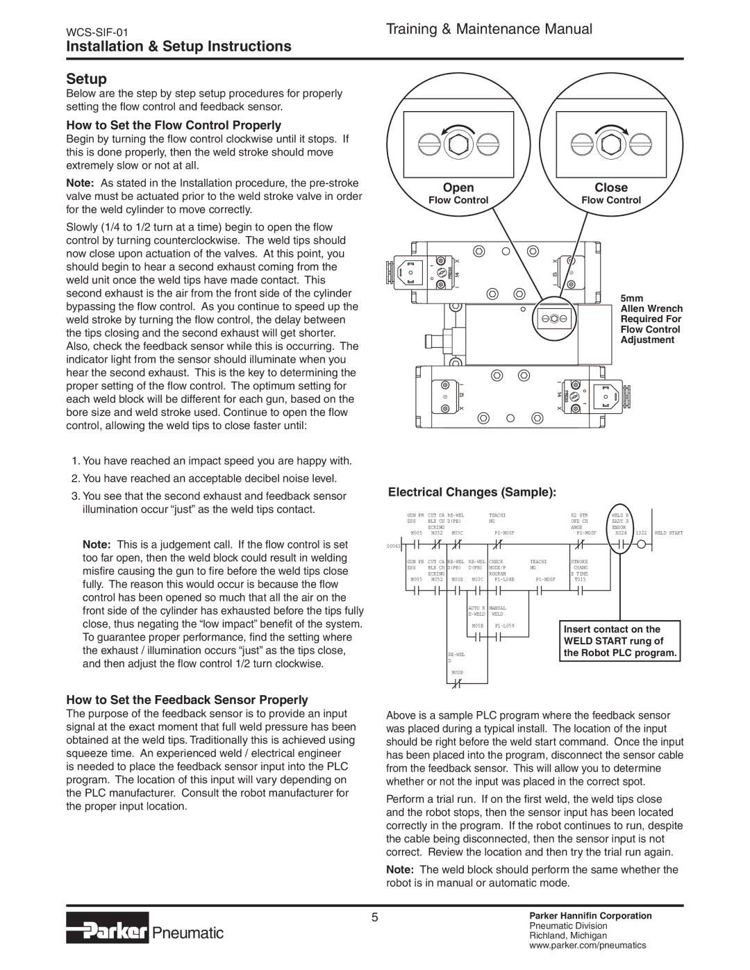
Open | Close |
Flow Control | Flow Control |
5mm
Allen Wrench Required For Flow Control Adjustment
Electrical Changes (Sample):
GUN PR | CUT CA | TEACHI | K2 STR | WELD R |
| |
ESS | BLE CH D(PB) | NG | OKE CH | EADY S |
| |
| ECKING |
|
| ANGE | ENSOR |
|
M005 | M052 | M03C | X024 | 1022 WELD START | ||
Note: This is a judgement call. If the flow control is set | 00061 |
too far open, then the weld block could result in welding misfire causing the gun to fire before the weld tips close fully. The reason this would occur is because the flow control has been opened so much that all the air on the front side of the cylinder has exhausted before the tips fully close, thus negating the “low impact” benefit of the system. To guarantee proper performance, find the setting where the exhaust / illumination occurs “just” as the tips close, and then adjust the flow control 1/2 turn clockwise.
GUN PR CUT CA | TEACHI | STROKE | |||
ESS | BLE CH D(PB) | D(PB) | MODE/P | NG | CHANG |
| ECKING |
| ROGRAM |
| E TIME |
M005 | M052 M00B | M03C | T015 | ||
|
| AUTO R | MANUAL |
|
|
|
| WELD |
|
| |
|
| M05B |
| Insert contact on the | |
|
|
|
|
| |
|
|
|
|
| WELD START rung of |
|
|
|
| the Robot PLC program. | |
| D |
|
|
|
|
| M00B |
|
|
|
|
How to Set the Feedback Sensor Properly
The purpose of the feedback sensor is to provide an input signal at the exact moment that full weld pressure has been obtained at the weld tips. Traditionally this is achieved using squeeze time. An experienced weld / electrical engineer is needed to place the feedback sensor input into the PLC program. The location of this input will vary depending on the PLC manufacturer. Consult the robot manufacturer for the proper input location.
Above is a sample PLC program where the feedback sensor was placed during a typical install. The location of the input should be right before the weld start command. Once the input has been placed into the program, disconnect the sensor cable from the feedback sensor. This will allow you to determine whether or not the input was placed in the correct spot.
Perform a trial run. If on the first weld, the weld tips close and the robot stops, then the sensor input has been located correctly in the program. If the robot continues to run, despite the cable being disconnected, then the sensor input is not correct. Review the location and then try the trial run again.
Note: The weld block should perform the same whether the robot is in manual or automatic mode.
 Pneumatic
Parker Hannifin Corporation Pneumatic Division Richland, Michigan www.parker.com/pneumatics