Training & Maintenance Manual |
Ordering Information
How To Order Add-A-Fold Assemblies
1.List
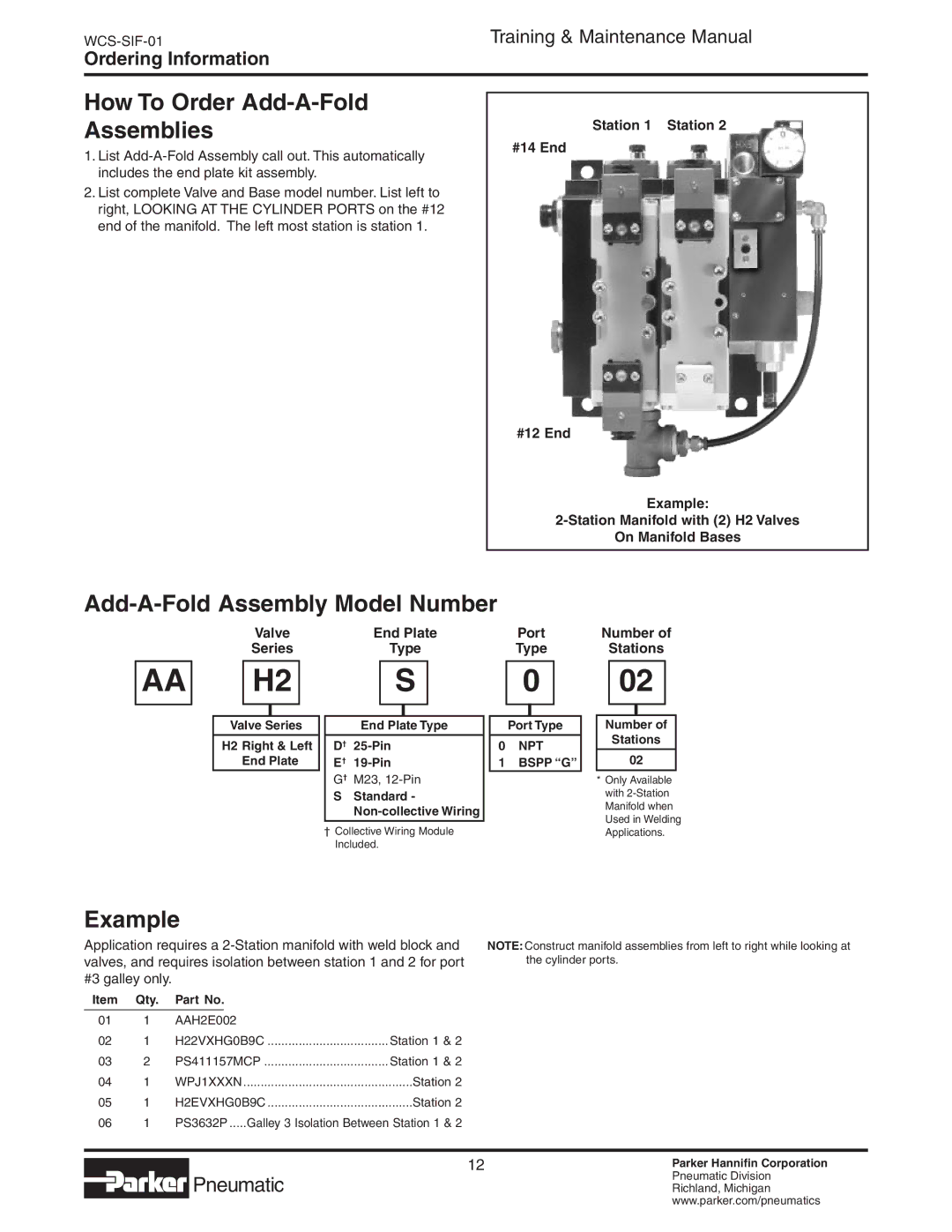
2.List complete Valve and Base model number. List left to right, looking at the cylinder ports on the #12 end of the manifold. The left most station is station 1.
Station 1 Station 2
#14 End
#12 End
Example:
On Manifold Bases
Add-A-Fold Assembly Model Number
AA
Valve | End Plate |
Series | Type |
| S |
H2 | |
|
|
Port
Type
0
Number of
Stations
02
Example
Valve Series
H2 Right & Left
End Plate
End Plate Type
D†
E†
G† M23,
SStandard -
†Collective Wiring Module Included.
Port Type
0NPT
1BSPP “G”
Number of
Stations
02
*Only Available with
Application requires a
Item Qty. Part No.
NOTE: Construct manifold assemblies from left to right while looking at the cylinder ports.
01 | 1 | AAH2E002 |
|
02 | 1 | H22VXHG0B9C | Station 1 & 2 |
03 | 2 | PS411157MCP | Station 1 & 2 |
04 | 1 | WPJ1XXXN | Station 2 |
05 | 1 | H2EVXHG0B9C | Station 2 |
06 | 1 | PS3632P......Galley 3 Isolation Between Station 1 & 2 | |
 Pneumatic
12Parker Hannifin Corporation
Pneumatic Division
Richland, Michigan
www.parker.com/pneumatics