Catalog | “N” Series Valves |
Dimensions - Single Solenoid | Internal Pilot - 3/8" & 3/4" Basic Body |
|
|
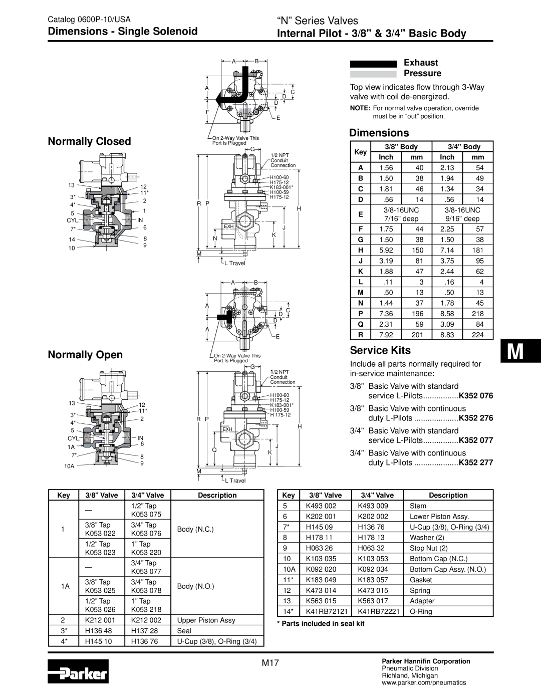
A | B | Exhaust | |
|
| Pressure | |
A | D C | Top view indicates flow through | |
| valve with coil | ||
| D | NOTE: For normal valve operation, override | |
F |
| ||
E | must be in “out” position. | ||
|
Normally Closed
13 | 12 | |
3* | 11* | |
2 | ||
4* | ||
1 | ||
5 | ||
| ||
CYL. | IN | |
7* | 6 | |
| ||
14 | 8 | |
10 | 9 | |
|
On
Port Is Plugged
![]() G
G![]()
1/2 NPT
Conduit
Connection
![]() H100-60
H100-60
![]()
![]() H175-12
H175-12
![]()
![]() K183-001*
K183-001*
![]()
![]()
R P
H
EXH | J |
N | K |
|
M |
![]() L Travel
L Travel
![]() A
A![]()
![]() B
B![]()
A
![]() D C
D C
D ![]()
A
E
Dimensions
Key | 3/8" Body | 3/4" Body | |||
Inch | mm | Inch | mm | ||
| |||||
A | 1.56 | 40 | 2.13 | 54 | |
B | 1.50 | 38 | 1.94 | 49 | |
C | 1.81 | 46 | 1.34 | 34 | |
D | .56 | 14 | .56 | 14 | |
E | |||||
7/16" deep | 9/16" deep | ||||
| |||||
F | 1.75 | 44 | 2.25 | 57 | |
G | 1.50 | 38 | 1.50 | 38 | |
H | 5.92 | 150 | 7.14 | 181 | |
J | 3.19 | 81 | 3.75 | 95 | |
K | 1.88 | 47 | 2.44 | 62 | |
L | .11 | 3 | .16 | 4 | |
M | .50 | 13 | .50 | 13 | |
N | 1.44 | 37 | 1.78 | 45 | |
P | 7.36 | 196 | 8.58 | 218 | |
Q | 2.31 | 59 | 3.09 | 84 | |
R | 7.92 | 201 | 8.83 | 224 | |
Normally Open
13 | 12 |
| 11* |
On
Port Is Plugged
![]() G
G![]()
1/2 NPT
Conduit
Connection
![]() H100-60
H100-60
![]()
![]()
![]()
![]()
![]()
![]()
![]()
![]() H100-59
H100-59
Service Kits
Include all parts normally required for
3/8" | Basic Valve with standard |
|
| service | K352 076 |
3/8" | Basic Valve with continuous | |
3* | 2 |
4* |
R P
![]() H
H
duty | K352 276 |
5 |
|
CYL. | IN |
1A | 6 |
| |
7* | 8 |
10A | 9 |
|
| EXH | H |
|
| |
Q |
| J |
| K | |
|
|
M |
3/4" | Basic Valve with standard |
|
| service | K352 077 |
3/4" | Basic Valve with continuous | |
| duty | K352 277 |
![]() L Travel
L Travel
Key | 3/8" Valve | 3/4" Valve | Description | |
| — | 1/2" Tap |
| |
| K053 075 |
| ||
|
|
| ||
1 | 3/8" Tap | 3/4" Tap | Body (N.C.) | |
K053 022 | K053 076 | |||
|
| |||
| 1/2" Tap | 1" Tap |
| |
| K053 023 | K053 220 |
| |
| — | 3/4" Tap |
| |
| K053 077 |
| ||
|
|
| ||
1A | 3/8" Tap | 3/4" Tap | Body (N.O.) | |
K053 025 | K053 078 | |||
|
| |||
| 1/2" Tap | 1" Tap |
| |
| K053 026 | K053 218 |
| |
2 | K212 001 | K212 002 | Upper Piston Assy | |
3* | H136 48 | H137 28 | Seal | |
4* | H145 10 | H136 76 |
Key | 3/8" Valve | 3/4" Valve | Description |
5 | K493 002 | K493 009 | Stem |
6 | K202 001 | K202 002 | Lower Piston Assy. |
7* | H145 09 | H136 76 | |
8 | H178 11 | H178 13 | Washer (2) |
9 | H063 26 | H063 32 | Stop Nut (2) |
10 | K103 035 | K103 053 | Bottom Cap (N.C.) |
10A | K092 020 | K092 034 | Bottom Cap Assy. (N.O.) |
11* | K183 049 | K183 057 | Gasket |
12 | K473 014 | K473 015 | Spring |
13 | K563 015 | K563 017 | Adapter |
14* | K41RB72121 | K41RB72221 |
* Parts included in seal kit
M17Parker Hannifin Corporation
Pneumatic Division
Richland, Michigan
www.parker.com/pneumatics