Catalog | “N” Series Valves |
Technical Information | Solenoid Characteristics |
|
|
Solenoid Characteristics Chart
Voltage Range +10/-15% of Nominal
3/8" & 3/4" Basic –
Voltage/ | Amps | Amps | Resistance |
| Insulation |
Cycles | Inrush | Holding | Ohms | Watts | Class |
|
|
|
|
|
|
120/60VAC | .29 | .18 | 122 | 12 | B |
|
|
|
|
|
|
110/50VAC | .21 | .14 | 122 | 12 | B |
|
|
|
|
|
|
240/60VAC | .18 | .12 | 610 | 12 | B |
|
|
|
|
|
|
24/60VAC | 1.6 | 1.0 | 4.5 | 9.5 | B |
|
|
|
|
|
|
24/50VAC | 1.2 | .75 | 6.4 | 9.5 | B |
|
|
|
|
|
|
6VDC | – | 1.4 | 4.5 | 7.6 | B |
|
|
|
|
|
|
12VDC | – | .66 | 17.7 | 9 | B |
|
|
|
|
|
|
24VDC | – | .32 | 71 | 9 | B |
|
|
|
|
|
|
48VDC | – | .22 | 216 | 11 | B |
|
|
|
|
|
|
Continuous Duty Pilots
Continuous duty pilots are designed for applications where cycling is infrequent and the pilot is to be energized for indefinite periods of time . . . hours, days or weeks. Typical uses include
The Continuous duty pilot operates satisfactorily in ambient temperatures up to 125°F, even when continuously energized and without the benefit of the cooling air which normally flows through the pilot during frequent cycling. Under certain conditions, satisfactory operation may be obtained at ambient temperatures above 125°F. CONSULT FACTORY.
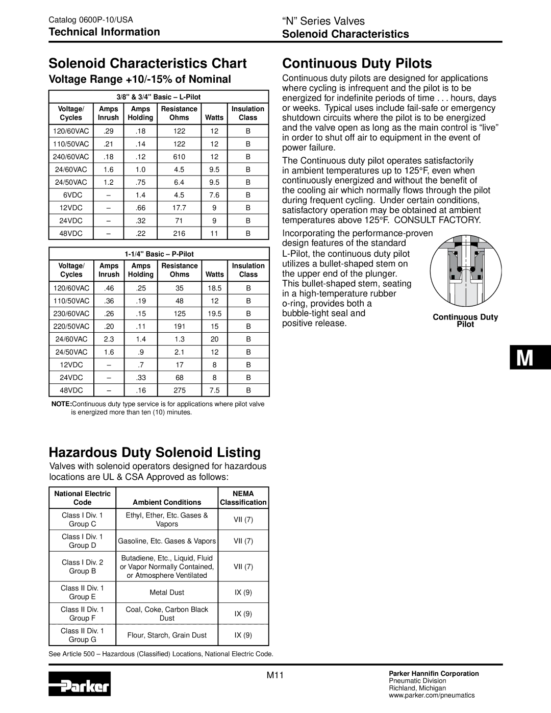
Incorporating the
Voltage/ | Amps | Amps | Resistance |
| Insulation |
Cycles | Inrush | Holding | Ohms | Watts | Class |
|
|
|
|
|
|
120/60VAC | .46 | .25 | 35 | 18.5 | B |
|
|
|
|
|
|
110/50VAC | .36 | .19 | 48 | 12 | B |
|
|
|
|
|
|
230/60VAC | .26 | .15 | 125 | 19.5 | B |
|
|
|
|
|
|
220/50VAC | .20 | .11 | 191 | 15 | B |
|
|
|
|
|
|
24/60VAC | 2.3 | 1.4 | 1.3 | 20 | B |
|
|
|
|
|
|
24/50VAC | 1.6 | .9 | 2.1 | 12 | B |
|
|
|
|
|
|
12VDC | – | .7 | 17 | 8 | B |
|
|
|
|
|
|
24VDC | – | .33 | 68 | 8 | B |
|
|
|
|
|
|
48VDC | – | .16 | 275 | 7.5 | B |
|
|
|
|
|
|
NOTE:Continuous duty type service is for applications where pilot valve is energized more than ten (10) minutes.
This
positive release.
Continuous Duty
Pilot
M |
Hazardous Duty Solenoid Listing
Valves with solenoid operators designed for hazardous locations are UL & CSA Approved as follows:
National Electric |
| NEMA | |
Code | Ambient Conditions | Classification | |
|
|
| |
Class I Div. 1 | Ethyl, Ether, Etc. Gases & | VII (7) | |
Group C | Vapors | ||
| |||
|
|
| |
Class I Div. 1 | Gasoline, Etc. Gases & Vapors | VII (7) | |
Group D | |||
|
| ||
|
|
| |
Class I Div. 2 | Butadiene, Etc., Liquid, Fluid |
| |
or Vapor Normally Contained, | VII (7) | ||
Group B | |||
or Atmosphere Ventilated |
| ||
|
| ||
|
|
| |
Class II Div. 1 | Metal Dust | IX (9) | |
Group E | |||
|
| ||
|
|
| |
Class II Div. 1 | Coal, Coke, Carbon Black | IX (9) | |
Group F | Dust | ||
| |||
|
|
| |
Class II Div. 1 | Flour, Starch, Grain Dust | IX (9) | |
Group G | |||
|
| ||
|
|
|
See Article 500 – Hazardous (Classified) Locations, National Electric Code.
M11Parker Hannifin Corporation
Pneumatic Division
Richland, Michigan
www.parker.com/pneumatics