Chiller Controller
Installation and Servicing Instructions
The Chiller Controller has the most features of any Sporlan controller. It will control one or two Sporlan Electric Expansion Valves, and con- trols superheat by means of
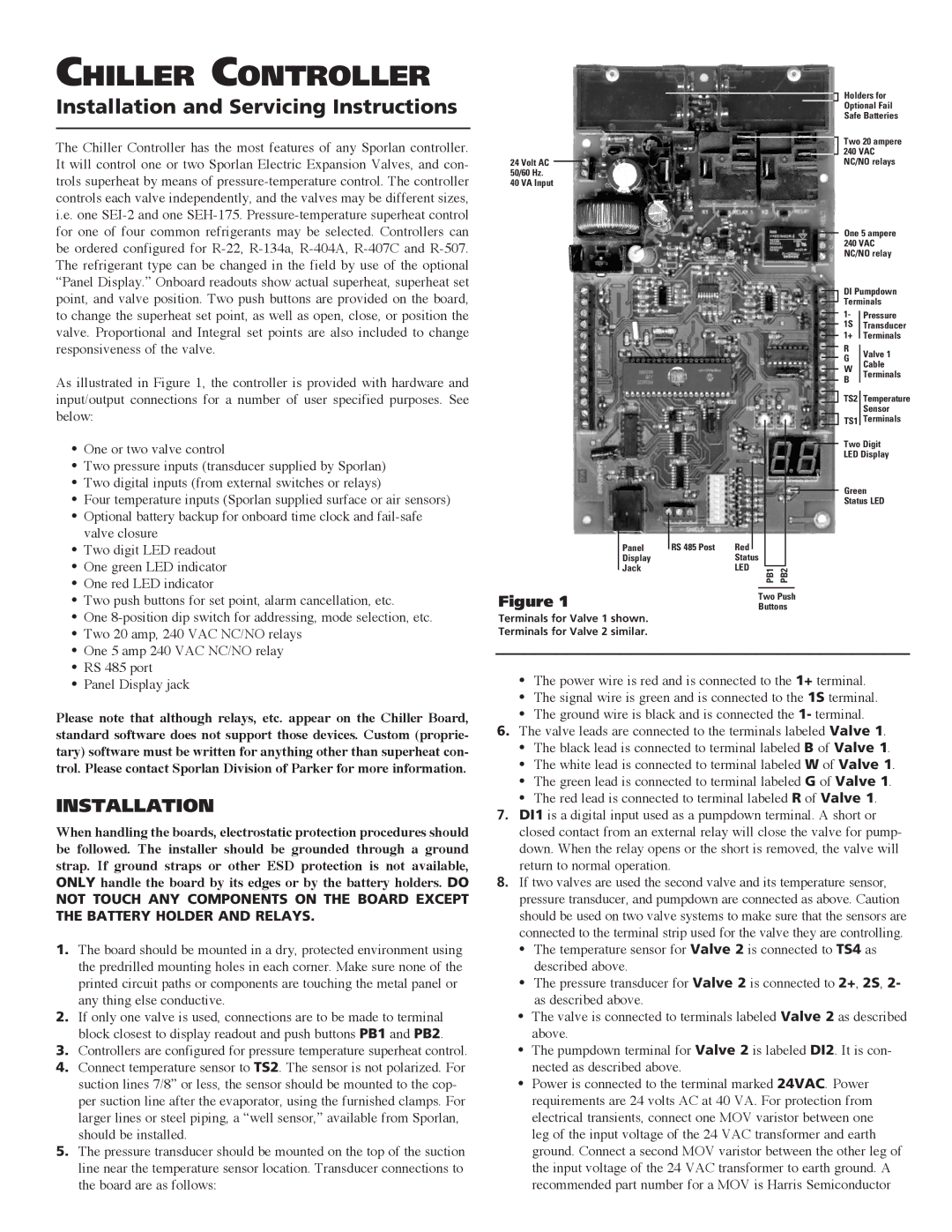
As illustrated in Figure 1, the controller is provided with hardware and input/output connections for a number of user specified purposes. See below:
• | One or two valve control |
• | Two pressure inputs (transducer supplied by Sporlan) |
• | Two digital inputs (from external switches or relays) |
• | Four temperature inputs (Sporlan supplied surface or air sensors) |
• | Optional battery backup for onboard time clock and |
• | valve closure |
Two digit LED readout | |
• | One green LED indicator |
• | One red LED indicator |
• | Two push buttons for set point, alarm cancellation, etc. |
• | One |
• | Two 20 amp, 240 VAC NC/NO relays |
• | One 5 amp 240 VAC NC/NO relay |
• | RS 485 port |
24 Volt AC
50/60 Hz.
40 VA Input
Panel
Display
Jack
Figure 1
Terminals for Valve 1 shown. Terminals for Valve 2 similar.
RS 485 Post | Red |
|
|
|
|
|
|
|
| ||
|
|
| |||
| Status |
|
| ||
| LED |
|
| ||
| PB1 | PB2 | |||
|
|
|
| ||
Two Push
Buttons
Holders for Optional Fail Safe Batteries
Two 20 ampere
240VAC NC/NO relays
One 5 ampere
240VAC NC/NO relay
DI Pumpdown Terminals
1- |
| Pressure |
| ||
1S |
| Transducer |
1+ |
| Terminals |
|
RValve 1
G Cable
W Terminals
B
TS2 Temperature
Sensor
TS1 Terminals
Two Digit
LED Display
Green
Status LED
• Panel Display jack |
Please note that although relays, etc. appear on the Chiller Board, standard software does not support those devices. Custom (proprie- tary) software must be written for anything other than superheat con- trol. Please contact Sporlan Division of Parker for more information.
INSTALLATION
When handling the boards, electrostatic protection procedures should be followed. The installer should be grounded through a ground strap. If ground straps or other ESD protection is not available, ONLY handle the board by its edges or by the battery holders. DO NOT TOUCH ANY COMPONENTS ON THE BOARD EXCEPT
THE BATTERY HOLDER AND RELAYS.
1.The board should be mounted in a dry, protected environment using the predrilled mounting holes in each corner. Make sure none of the printed circuit paths or components are touching the metal panel or any thing else conductive.
2.If only one valve is used, connections are to be made to terminal block closest to display readout and push buttons PB1 and PB2.
3.Controllers are configured for pressure temperature superheat control.
4.Connect temperature sensor to TS2. The sensor is not polarized. For suction lines 7/8” or less, the sensor should be mounted to the cop- per suction line after the evaporator, using the furnished clamps. For larger lines or steel piping, a “well sensor,” available from Sporlan, should be installed.
5.The pressure transducer should be mounted on the top of the suction line near the temperature sensor location. Transducer connections to the board are as follows:
•The power wire is red and is connected to the 1+ terminal.
•The signal wire is green and is connected to the 1S terminal.
•The ground wire is black and is connected the 1- terminal.
6.The valve leads are connected to the terminals labeled Valve 1.
•The black lead is connected to terminal labeled B of Valve 1.
•The white lead is connected to terminal labeled W of Valve 1.
•The green lead is connected to terminal labeled G of Valve 1.
•The red lead is connected to terminal labeled R of Valve 1.
7.DI1 is a digital input used as a pumpdown terminal. A short or closed contact from an external relay will close the valve for pump- down. When the relay opens or the short is removed, the valve will return to normal operation.
8.If two valves are used the second valve and its temperature sensor, pressure transducer, and pumpdown are connected as above. Caution should be used on two valve systems to make sure that the sensors are connected to the terminal strip used for the valve they are controlling.
•The temperature sensor for Valve 2 is connected to TS4 as described above.
•The pressure transducer for Valve 2 is connected to 2+, 2S, 2- as described above.
•The valve is connected to terminals labeled Valve 2 as described above.
•The pumpdown terminal for Valve 2 is labeled DI2. It is con- nected as described above.
•Power is connected to the terminal marked 24VAC. Power requirements are 24 volts AC at 40 VA. For protection from electrical transients, connect one MOV varistor between one leg of the input voltage of the 24 VAC transformer and earth ground. Connect a second MOV varistor between the other leg of the input voltage of the 24 VAC transformer to earth ground. A recommended part number for a MOV is Harris Semiconductor