Page 4
Pressing the UP button will increase the set point by 1 unit. Pressing the DOWN button will decrease the set point by 1 unit. Pressing the ENTER button will change the flashing digit from 1’s digit to the 100’s digit.
Press and hold the UP button and ENTER button together for 5 seconds to save the set point. The digits will stop blinking.
CHANGING REFRIGERANTS
Press and hold the UP button and ENTER button simultaneously for 5 seconds to enable the controller to change to another type of refrigerant. All 4 digits will start to blink.
Pressing the UP button or the DOWN button will change the display to other refrigerants.
When the display shows the desired refrigerant, press and hold the UP button and ENTER button for together 5 seconds. The controller will save and use the selected refrigerant’s table for saturated temperature. The digits will stop blinking.
CHANGING VALVE TYPES – LGE1, SML1, or MED1
Press and hold the UP button and ENTER button for 5 seconds to enable the controller to change to the other type of valves. All 4 digits will start to blink.
Pressing either the UP button or the DOWN button will change the dis- play between the different valve types. Press and hold the UP button and ENTER button together for 5 seconds to save the selection. The digits will stop blinking.
Pressing the UP button and the DOWN button simultaneously will toggle the display between AC circuit 1 and AC circuit 2.
AC CIRCUIT 2 MENU
The preceding instructions apply to AC circuit 2 as well as AC circuit 1:
SUP2 Superheat read by controller for AC circuit 2
POS2 Number of steps valve is open
circuit 2
TMP2 Temperature read by the temperature sensor
TST2 Saturated temperature for AC circuit 2
AC2, PDN2
AC2 when in normal operation, PDN2 when in pumpdown for AC circuit 2
R22, 134A, 407C, 404A, R507
R22 for refrigerant
LGE2, SML2, MED2, ESX2
LGE2 if the EEV used is an
ESX2 if the EEV used is a ESX for AC circuit 2.
SSP2 Superheat set point (0 to 16°F) for AC circuit 2. Default is 10°F.
MOP2 Maximum operating suction pressure set point (0 to 153 PSI) for AC circuit 2. Default is 153 PSI.
CTS2 Cut out suction pressure set point for AC circuit 2 (0 to 153 PSI) CLP2 Calibrate pressure transducer for AC circuit 2
CLT2 Calibrate temperature sensor for AC circuit 2
PRO2 Proportional gain set point for AC circuit 2. Number of steps per degree that superheat is above or below the superheat set point (5 to 255 steps per degree). Default is 45 for the LGE2 setting, 22 for the MED2 setting, or 11 for the SML2 setting.
INT2 Integral set point for AC circuit 2. Number of seconds the con- troller waits to update the reference valve position. (1 to 120 seconds). Default is 10 seconds.
DER2 Derivative setpoint for valve 2. Advanced algorithm parameter that determines the slope of the change control point. Default is zero.
DON2 Time delay in seconds between end of pumpdown and com- pressor start when Relay 1 is used to pilot the compressor con- tactor. The
DOF2 Time in seconds that the valve is shut before the compressor Relay 1 opens to stop the compressor. Allows refrigerant pump- down/pumpout. Default is 2 seconds.
DST2 Used with DON2. Number of steps to
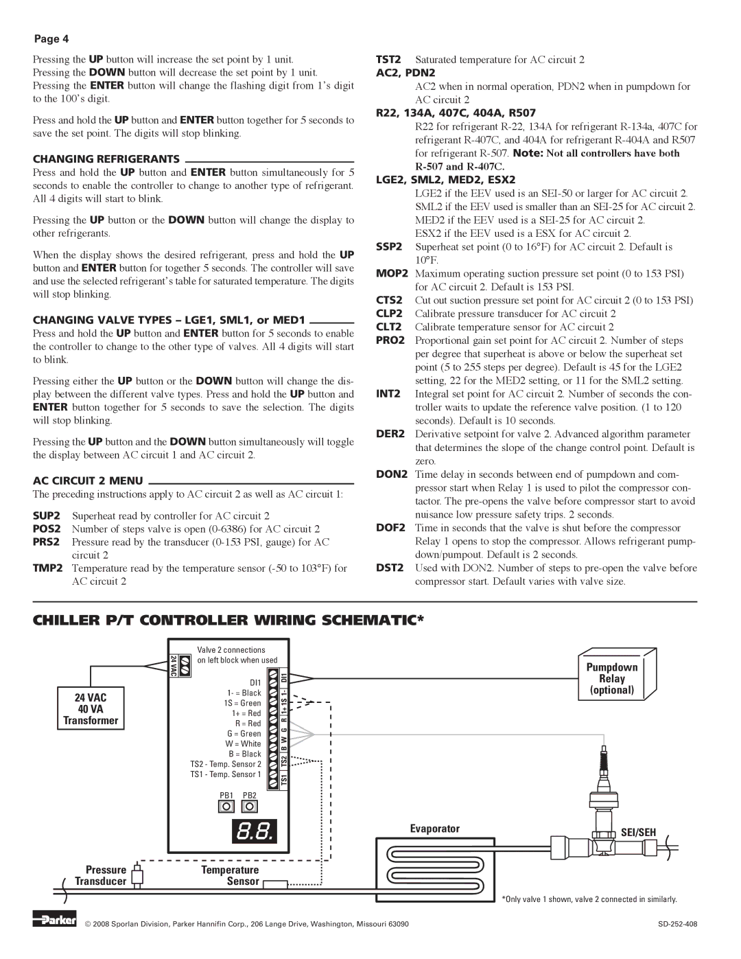
CHILLER P/T CONTROLLER WIRING SCHEMATIC*
24VAC 40 VA
Transformer
Pressure  Transducer
24 VAC![]()
![]()
Valve 2 connections
on left block when used
DI1
1- = Black
1S = Green
1+ = Red
R = Red
G = Green
W = White
B = Black
TS2 - Temp. Sensor 2
TS1 - Temp. Sensor 1
PB1 PB2
 TS1 TS2 B W G R 1+ 1S 1- DI1

8.8.Evaporator
Temperature
Sensor ![]()
Pumpdown
Relay
(optional)
 SEI/SEH
*Only valve 1 shown, valve 2 connected in similarly.
© 2008 Sporlan Division, Parker Hannifin Corp., 206 Lange Drive, Washington, Missouri 63090 |