VO40 specifications
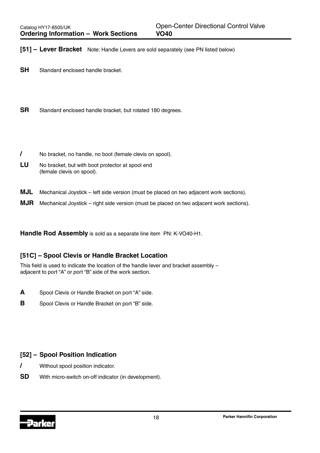
Parker Hannifin's VO40 is a sophisticated and versatile hydraulic valve that has garnered attention for its innovative design and wide-ranging applications. Designed to meet the increasing demands for efficiency and reliability in various industrial and mobile machinery, the VO40 series exemplifies Parker's commitment to providing high-performance solutions.One of the primary features of the VO40 is its compact design, which allows for easy integration into systems with limited space. This is accomplished without sacrificing performance, as the valve delivers exceptional flow rates, which can significantly enhance the efficiency of hydraulic systems. The VO40's multi-functionality enables it to serve diverse roles, from directional control to flow regulation, making it suitable for a variety of hydraulic applications.
The VO40 utilizes advanced technologies, including modular construction, which provides flexibility for different system configurations. This modularity allows users to customize the valve to their specific requirements, whether they need a simple on/off control or more complex, proportional flow regulation. The valve's design also incorporates electronic control capabilities, enabling users to achieve precise movements and optimize system performance.
In terms of materials, the VO40 is constructed from robust components to withstand high-pressure operations and harsh environments. The valve's sealing technology is engineered for durability and reliability, minimizing the risk of leaks and prolonging the service life of the product. This reliability is a critical factor in reducing maintenance costs and ensuring operational continuity in demanding applications.
Another significant characteristic of the VO40 is its ease of installation and maintenance. The design allows for quick assembly and disassembly, which is crucial for minimizing downtime during maintenance activities. Additionally, the valve features diagnostic capabilities, enabling operators to monitor performance and address potential issues proactively.
In conclusion, the Parker Hannifin VO40 hydraulic valve stands out in the marketplace due to its compact size, modularity, advanced electronic controls, and robust construction. Its design and technology make it an ideal choice for users seeking reliable and efficient solutions for their hydraulic systems. By integrating the VO40 into their operations, companies can enhance productivity while ensuring a long-lasting, low-maintenance hydraulic solution.

