Manuals
/
Patterson-Kelley
/
Household Appliance
/
Boiler
Patterson-Kelley
DVSCM-02
owner manual
On-Off Auxiliary Control Panel
Models:
DVSCM-02
1
25
26
26
Download
26 pages
5.4 Kb
19
20
21
22
23
24
25
26
Install
Wiring Diagrams
Maintenance
Safety
Page 25
Image 25
Thermific
®
Gas-Fired
Boiler
Wiring Diagrams
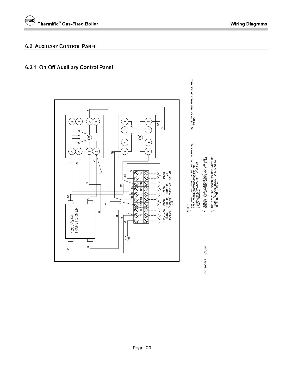
6.2
A
UXILIARY
C
ONTROL
P
ANEL
6.2.1
On-Off
Auxiliary Control Panel
Page 23
Page 24
Page 26
Page 25
Image 25
Page 24
Page 26
Contents
Direct Vent
What to do if you smell gas
Direct Vent/Sealed Combustion System
Introduction
Fresh Air System
Roof Exhaust Vent Sidewall Air Inlet
Safety
System Design Pressure Drop
Installation
Inlet Duct
Air Inlet Termination
Unrestricted Rain cap
Inlet Duct Assembly at the Boiler
System Design Materials, Length, Size, and Construction
Inlet Damper and Auxiliary Control Panel optional
Flue Gas Outlet Duct
Flue Gas Termination
Exhaust Vent Connection at the Boiler
Equivalent Length of Fittings
Sidewall Installations
Combustion Min Air Inlet Above Snow line Flue Gas Outlet
Minimum Clearance for Boiler Connections
Round Vent Damper 90o Elbow
Operation
Combustion Air Requirement, Scfm
Maintenance
ON-OFFSERIES 700, 1000
Wiring Diagrams
Logic Diagram
1A ON-OFFIRI Series 700, 1000
1A ON-OFFIRI Series 700, 1000
1B LO-HILO
1B LO-HILO
1C LO-HI-LOIRI
1C LO-HI-LOIRI
1D ON-OFFSERIES 1500, 1700
1D ON-OFFSERIES 1500, 1700
1E ON-OFFIRI Series 1500, 1700
1E ON-OFFIRI Series 1500, 1700
On-Off Auxiliary Control Panel
Top
Page
Image
Contents