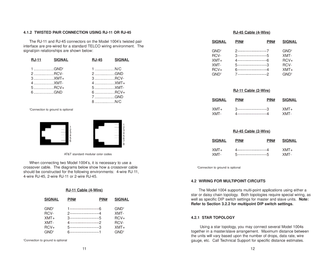
4.1.2 TWISTED PAIR CONNECTION USING RJ-11 OR RJ-45
The
SIGNAL | SIGNAL | ||
1 | GND† | 1 | N/C |
2 | RCV- | 2 | GND |
3 | XMT+ | 3 | RCV- |
4 | XMT- | 4 | XMT+ |
5 | RCV+ | 5 | XMT- |
6 | GND | 6 | RCV+ |
|
| 7 | GND |
|
| 8 | N/C |
†Connection to ground is optional |
|
| |
| 1 |
| 1 |
|
| 2 | |
| 2 |
| 3 |
| 3 |
| 4 |
| 4 |
| 5 |
| 5 |
| 6 |
| 6 |
| 7 |
|
|
| 8 |
AT&T standard modular color codes
When connecting two Model 1004’s, it is necessary to use a
crossover cable. The diagrams below show how a crossover cable should be constructed for the following environments:
|
| ||
SIGNAL | PIN# | PIN# | SIGNAL |
GND† | 6 | GND† | |
RCV- | 4 | XMT- | |
XMT+ | 5 | RCV+ | |
XMT- | 2 | RCV- | |
RCV+ | 3 | XMT+ | |
GND† | 1 | GND† | |
†Connection to ground is optional
11
|
| ||
SIGNAL | PIN# | PIN# | SIGNAL |
GND† | 7 | GND† | |
RCV- | 5 | XMT- | |
XMT+ | 6 | RCV+ | |
XMT- | 3 | RCV- | |
RCV+ | 4 | XMT+ | |
GND† | 2 | GND† | |
|
| ||
SIGNAL | PIN# | PIN# | SIGNAL |
XMT+ | 3 | XMT+ | |
XMT- | 4 | XMT- | |
|
| ||
SIGNAL | PIN# | PIN# | SIGNAL |
XMT+ | 4 | XMT+ | |
XMT- | 5 | XMT- | |
†Connection to ground is optional
4.2 WIRING FOR MULTIPOINT CIRCUITS
The Model 1004 supports
Refer to Section 3.2.2 for multipoint DIP switch settings.
4.2.1 STAR TOPOLOGY
Using a star topology, you may connect several Model 1004s together in a master/slave arrangement. Maximum distance between the units will vary based upon the number of drops, data rate, wire gauge, etc. Call Technical Support for specific distance estimates.
12