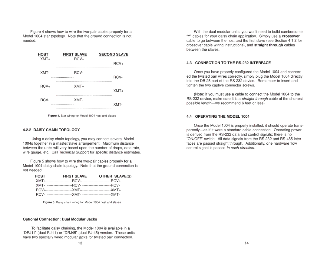
Figure 4 shows how to wire the two-pair cables properly for a Model 1004 star topology. Note that the ground connection is not needed.
HOST | FIRST SLAVE | SECOND SLAVE |
XMT+RCV+
RCV+
XMT-RCV-
RCV-
RCV+XMT+
XMT+
RCV-XMT-
XMT-
Figure 4. Star wiring for Model 1004 host and slaves
4.2.2 DAISY CHAIN TOPOLOGY
Using a daisy chain topology, you may connect several Model 1004s together in a master/slave arrangement. Maximum distance between the units will vary based upon the number of drops, data rate, wire gauge, etc. Call Technical Support for specific distance estimates.
Figure 5 shows how to wire the two-pair cables properly for a Model 1004 daisy chain topology. Note that the ground connection is not needed.
HOST | FIRST SLAVE | OTHER SLAVE(S) |
XMT+ | RCV+ | |
XMT- | RCV- | |
RCV+ | XMT+ | |
RCV- | XMT- |
Figure 5. Daisy chain wiring for Model 1004 host and slaves
Optional Connection: Dual Modular Jacks
To facilitate daisy chaining, the Model 1004 is available in a “DRJ11” (dual
13
With the dual modular units, you won't need to build cumbersome “Y” cables for your daisy chain application. Simply use a crossover cable to go between the host and the first slave (see Section 4.1.2 for crossover cable wiring instructions), and straight through cables between the slaves.
4.3 CONNECTION TO THE RS-232 INTERFACE
Once you have properly configured the Model 1004 and connect- ed the twisted pair wires correctly, simply plug the Model 1004 directly into the
(Note: If you must use a cable to connect the Model 1004 to the
4.4 OPERATING THE MODEL 1004
Once the Model 1004 is properly installed, it should operate trans-
14