APPENDIX A
SPECIFICATIONS
Transmission Format: Asynchronous
Data Rate: Up to 115,200 bps
Transmit Line: 2, 4 wire unconditioned twisted pair
Transmit Mode: Full or half duplex
Transmit Level: 0 dBm
Range: Up to 9 miles
Control Signals: In DCE mode, DSR turns “ON” immediately after the terminal raises DTR; DCD turns “ON” after recogniz ing the receive signal from the line; CTS turns on after the terminal raises RTS
Carrier: The carrier is switch selected either continuous operation or switched operation, controlled by RTS
Surge Protection: 600W power dissipation at 1 mS and response time less than 1.0 pS
Power: No external power required, uses ultra low power from EIA data and control signals
Size: 2.66” x 2.10” x 0.73”
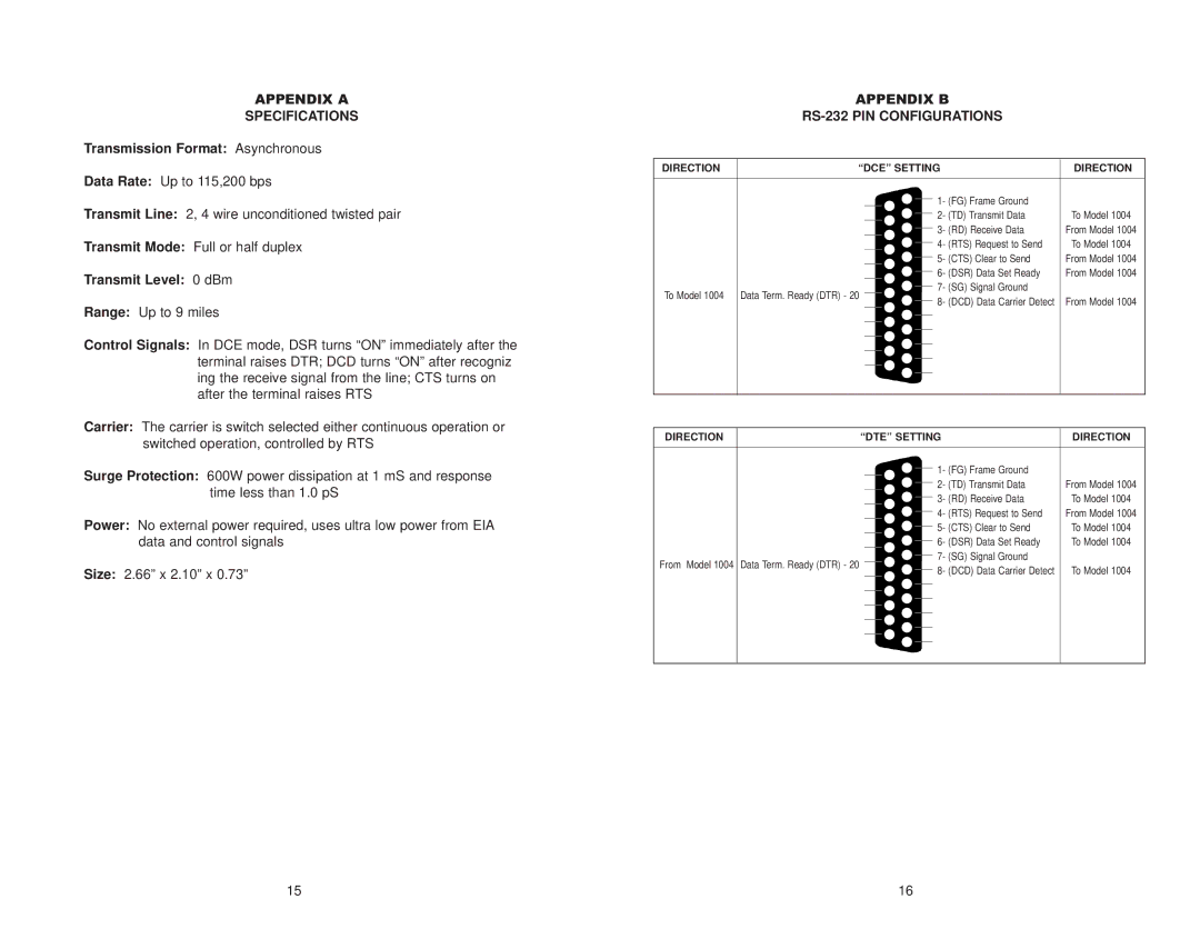
APPENDIX B
RS-232 PIN CONFIGURATIONS
DIRECTION | “DCE” SETTING |
| DIRECTION |
| ||||||
|
|
|
|
|
|
|
|
|
|
|
|
|
|
|
|
|
|
|
|
|
|
|
|
|
|
|
|
|
|
|
|
|
|
|
|
|
|
|
|
| 1- (FG) Frame Ground |
|
|
|
|
|
|
|
|
|
|
|
| |
|
|
|
|
|
|
|
| 2- (TD) Transmit Data | To Model 1004 |
|
|
|
|
|
|
|
|
|
| ||
|
|
|
|
|
|
|
| 3- (RD) Receive Data | From Model 1004 |
|
|
|
|
|
|
|
|
|
| ||
|
|
|
|
|
|
|
| 4- (RTS) Request to Send | To Model 1004 |
|
|
|
|
|
|
|
|
|
| ||
|
|
|
|
|
|
|
| 5- (CTS) Clear to Send | From Model 1004 |
|
|
|
|
|
|
|
|
|
| ||
|
|
|
|
|
|
|
| 6- (DSR) Data Set Ready | From Model 1004 |
|
|
|
|
|
|
|
|
|
| ||
|
|
|
|
|
|
|
| 7- (SG) Signal Ground |
|
|
|
|
|
|
|
|
|
|
|
| |
| To Model 1004 | Data Term. Ready (DTR) - 20 |
|
|
|
|
|
|
| |
|
|
|
|
|
| 8- (DCD) Data Carrier Detect | From Model 1004 |
| ||
|
|
|
|
|
|
|
|
| ||
|
|
|
|
|
|
|
|
|
|
|
|
|
|
|
|
|
|
|
|
|
|
|
|
|
|
|
|
|
|
|
|
|
|
|
|
|
|
|
|
|
|
|
|
|
|
|
|
|
|
|
|
|
|
|
|
|
|
|
|
|
|
|
|
|
|
|
|
|
|
|
|
|
|
|
|
|
|
|
|
|
|
|
|
|
|
|
|
|
|
|
|
|
|
|
|
|
|
|
|
|
|
|
|
|
|
|
|
|
|
|
|
|
|
|
|
|
|
|
|
|
| DIRECTION |
| “DTE” SETTING | DIRECTION | ||||||
|
|
|
|
|
|
|
|
|
|
|
|
|
|
|
|
|
|
|
|
|
|
|
|
|
|
|
|
|
|
|
|
|
|
|
|
|
|
|
|
| 1- (FG) Frame Ground |
|
|
|
|
|
|
|
|
|
|
|
| |
|
|
|
|
|
|
|
| 2- (TD) Transmit Data | From Model 1004 |
|
|
|
|
|
|
|
|
| |||
|
|
|
|
|
|
|
| 3- (RD) Receive Data | To Model 1004 |
|
|
|
|
|
|
|
|
| |||
|
|
|
|
|
|
|
| 4- (RTS) Request to Send | From Model 1004 |
|
|
|
|
|
|
|
|
| |||
|
|
|
|
|
|
|
| 5- (CTS) Clear to Send | To Model 1004 |
|
|
|
|
|
|
|
|
| |||
|
|
|
|
|
|
|
| 6- (DSR) Data Set Ready | To Model 1004 |
|
|
|
|
|
|
|
|
| |||
|
|
|
|
|
|
|
| 7- (SG) Signal Ground |
|
|
|
|
|
|
|
|
|
|
|
| |
| From Model 1004 | Data Term. Ready (DTR) - 20 |
|
|
|
|
|
|
| |
|
|
|
|
|
| 8- (DCD) Data Carrier Detect | To Model 1004 |
| ||
|
|
|
|
|
|
|
|
| ||
|
|
|
|
|
|
|
|
|
|
|
|
|
|
|
|
|
|
|
|
|
|
|
|
|
|
|
|
|
|
|
|
|
|
|
|
|
|
|
|
|
|
|
|
|
|
|
|
|
|
|
|
|
|
|
|
|
|
|
|
|
|
|
|
|
|
|
|
|
|
|
|
|
|
|
|
|
|
|
|
|
|
|
|
|
|
|
|
|
|
|
|
|
|
|
|
|
|
|
|
|
|
|
|
|
|
|
|
|
|
|
|
|
|
|
|
|
|
|
|
|
15 | 16 |
