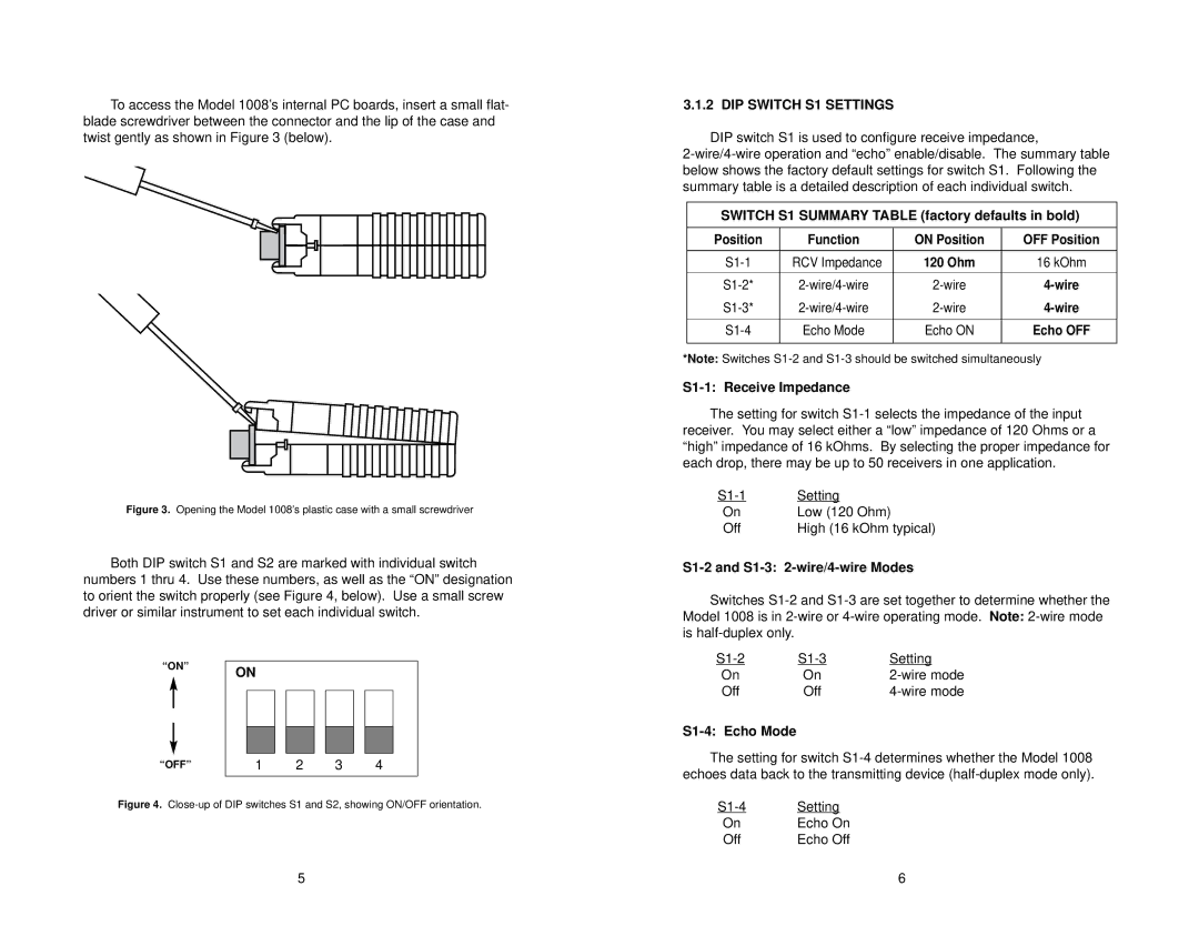
To access the Model 1008’s internal PC boards, insert a small flat- blade screwdriver between the connector and the lip of the case and twist gently as shown in Figure 3 (below).
Figure 3. Opening the Model 1008’s plastic case with a small screwdriver
Both DIP switch S1 and S2 are marked with individual switch numbers 1 thru 4. Use these numbers, as well as the “ON” designation to orient the switch properly (see Figure 4, below). Use a small screw driver or similar instrument to set each individual switch.
“ON” | ON |
|
“OFF” | 1 | 2 | 3 | 4 |
Figure 4. Close-up of DIP switches S1 and S2, showing ON/OFF orientation.
3.1.2 DIP SWITCH S1 SETTINGS
DIP switch S1 is used to configure receive impedance,
SWITCH S1 SUMMARY TABLE (factory defaults in bold)
Position | Function | ON Position | OFF Position |
|
|
|
|
RCV Impedance | 120 Ohm | 16 kOhm | |
|
|
|
|
|
|
|
|
Echo Mode | Echo ON | Echo OFF | |
|
|
|
|
*Note: Switches
S1-1: Receive Impedance
The setting for switch
Setting | |
On | Low (120 Ohm) |
Off | High (16 kOhm typical) |
S1-2 and S1-3: 2-wire/4-wire Modes
Switches
Setting | ||
On | On | |
Off | Off |
S1-4: Echo Mode
The setting for switch
Setting | |
On | Echo On |
Off | Echo Off |
5 | 6 |