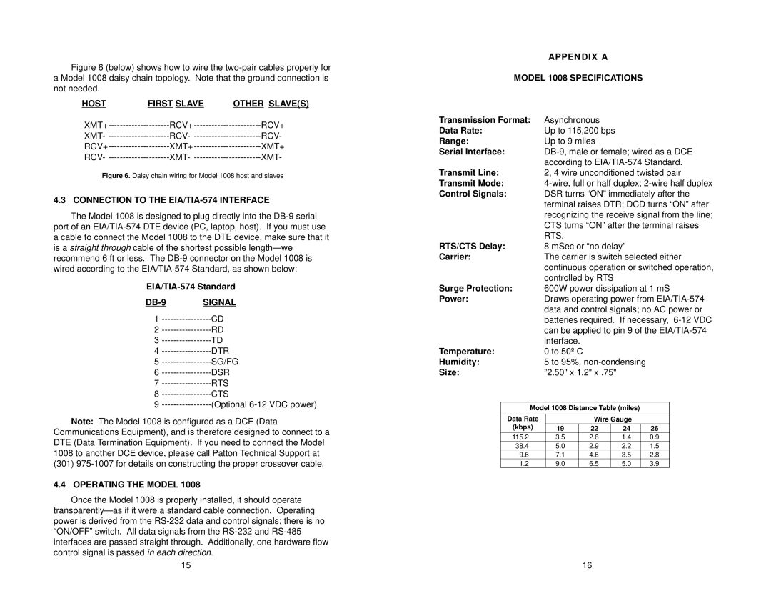
Figure 6 (below) shows how to wire the two-pair cables properly for a Model 1008 daisy chain topology. Note that the ground connection is not needed.
HOST | FIRST SLAVE | OTHER SLAVE(S) |
XMT+ | RCV+ | |
XMT- | RCV- | |
RCV+ | XMT+ | |
RCV- | XMT- |
Figure 6. Daisy chain wiring for Model 1008 host and slaves
4.3 CONNECTION TO THE EIA/TIA-574 INTERFACE
The Model 1008 is designed to plug directly into the
DB-9 SIGNAL
1
2
3
4
5
6
7
8
9
Note: The Model 1008 is configured as a DCE (Data Communications Equipment), and is therefore designed to connect to a DTE (Data Termination Equipment). If you need to connect the Model 1008 to another DCE device, please call Patton Technical Support at (301)
4.4 OPERATING THE MODEL 1008
Once the Model 1008 is properly installed, it should operate
15
APPENDIX A
MODEL 1008 SPECIFICATIONS
Transmission Format: | Asynchronous |
|
|
|
| ||||
Data Rate: | Up to 115,200 bps |
|
|
|
| ||||
Range: | Up to 9 miles |
|
|
|
| ||||
Serial Interface: | |||||||||
|
| according to | |||||||
Transmit Line: | 2, 4 wire unconditioned twisted pair | ||||||||
Transmit Mode: | |||||||||
Control Signals: | DSR turns “ON” immediately after the | ||||||||
|
| terminal raises DTR; DCD turns “ON” after | |||||||
|
| recognizing the receive signal from the line; | |||||||
|
| CTS turns “ON” after the terminal raises | |||||||
|
| RTS. |
|
|
|
|
|
| |
RTS/CTS Delay: | 8 mSec or “no delay” |
|
| ||||||
Carrier: | The carrier is switch selected either | ||||||||
|
| continuous operation or switched operation, | |||||||
|
| controlled by RTS |
|
|
|
| |||
Surge Protection: | 600W power dissipation at 1 mS | ||||||||
Power: | Draws operating power from | ||||||||
|
| data and control signals; no AC power or | |||||||
|
| batteries required. If necessary, | |||||||
|
| can be applied to pin 9 of the | |||||||
|
| interface. |
|
|
|
|
|
| |
Temperature: | 0 to 50º C |
|
|
|
|
|
| ||
Humidity: | 5 to 95%, |
|
| ||||||
Size: | ”2.50" x 1.2" x .75" |
|
|
|
| ||||
|
|
|
|
|
|
|
| ||
| Model 1008 Distance Table (miles) |
|
| ||||||
|
|
|
|
|
|
|
|
| |
| Data Rate |
|
| Wire Gauge |
|
| |||
| (kbps) | 19 |
| 22 |
| 24 |
| 26 |
|
| 115.2 | 3.5 |
| 2.6 |
| 1.4 |
| 0.9 |
|
| 38.4 | 5.0 |
| 2.9 |
| 2.2 |
| 1.5 |
|
| 9.6 | 7.1 |
| 4.6 |
| 3.5 |
| 2.8 |
|
| 1.2 | 9.0 |
| 6.5 |
| 5.0 |
| 3.9 |
|
16
