3.0 CONFIGURATION
The Model 1110 is simple to install and is ruggedly designed for excellent reliability: just set it and forget it. This section will describe how to configure the Model 1110’s DCE/DTE switch and how to set the internal DIP switches.
3.1 SETTING THE EXTERNAL DCE/DTE SWITCH
For your convenience, the Model 1110 has an externally accessible DCE/DTE switch (see Figure 1, below). If the device connected to the Model 1110 is a PC, terminal or host computer (or is wired like one), set the switch to “DCE”. This causes the Model 1110 to behave like Data Communications Equipment and transmit data on pin
3.If the device connected to the Model 1110 is a modem or multiplexer (or is wired like one), set the switch to “DTE”. This setting causes the Model 1110 to behave like Data Terminal Equipment and transmit data on pin 2.
|
|
|
|
|
|
| DCE |
|
| DTE |
|
|
|
|
| ||
|
|
|
|
|
|
|
|
|
|
|
|
|
|
|
|
|
|
Figure 1 Externally accessible DCE/DTE switch
3.2 SETTING INTERNAL DIP SWITCHES
The Model 1110‘s eight external DIP switches allow configuration of flow control and LED options. To set the internal switches, follow these steps:
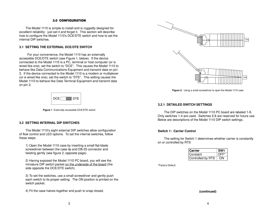
1)Open the Model 1110 case by inserting a small
2)Having exposed the Model 1110 PC board, you will see the miniature DIP switch packet on the underside of the board (the side opposite the DCE/DTE switch).
3)To set the switches, use a small screwdriver and gently push each switch to its proper setting. The ON position is printed on the switch packet.
4)Fit the case halves together and push to snap closed.
Figure 2. Using a small screwdriver to open the Model 1110 case
3.2.1 DETAILED SWITCH SETTINGS
The DIP switches on the Model 1110 PC board are labeled
Switch 1: Carrier Control
The setting for Switch 1 determines whether carrier is constantly on or controlled by RTS
|
|
Carrier | SW1 |
Constant | OFF* |
Controlled by RTS | ON |
*Factory Default
(continued)
3 | 4 |
