Switches 2 & 3: RTS/CTS Delay
The settings for Switches 2 & 3 determine whether the RTS/CTS delay will be 0 mS, 79.5 mS or 9.5 mS.
RTS/CTS Delay | SW2 | SW3 | |
|
|
|
|
0 mS | OFF | OFF | |
79.5 mS | ON | OFF |
|
9.5 mS | ON* | ON* |
|
|
|
|
|
*Factory Default
Switch 4: Enable Carrier Detect LED
The setting for Switch 4 determines whether the Model 1110 “carrier detect” LED indicator is enabled . When enabled, the carrier detect LED will glow red if a proper carrier frequency is recognized.
Carrier Detect LED | SW4 |
Enabled | ON* |
Disabled | OFF |
|
|
|
|
*Factory Default
Switches 5 through 8 : Future Use
4.0 INSTALLATION
The Model 1110 is easy to install. After configuring the DIP switches, simply connect the two fiber cables and then connect the
LEDs
Fiber | Fiber |
Figure 3. Rear panel of the Model 1110, showing fiber connections
4.1 FIBER CONNECTIONS
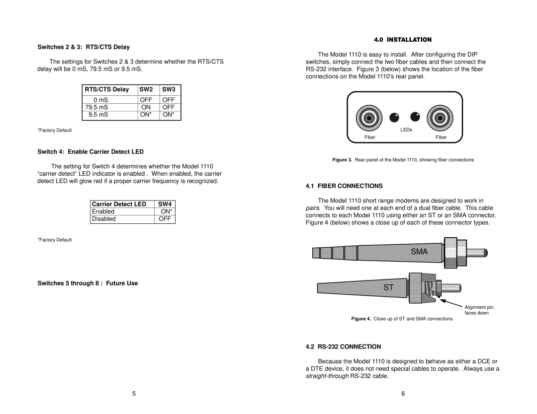
The Model 1110 short range modems are designed to work in pairs. You will need one at each end of a dual fiber cable. This cable connects to each Model 1110 using either an ST or an SMA connector. Figure 4 (below) shows a close up of each of these connector types.
SMA
ST
Alignment pin faces down
Figure 4. Close up of ST and SMA connections
4.2 RS-232 CONNECTION
Because the Model 1110 is designed to behave as either a DCE or a DTE device, it does not need special cables to operate. Always use a
5 | 6 |