2.3 TYPICAL APPLICATION
The
Corporate Headquarters
Model
LAN
2-Wire Leased Line
Remote/Satellite Office
Model
LAN
Figure 1. Typical Application
3.0 INSTALLATION
The Model 2111 requires no configuration. You only need to con- nect the Ethernet interface, line interface between the units and power. This section describes these connections.
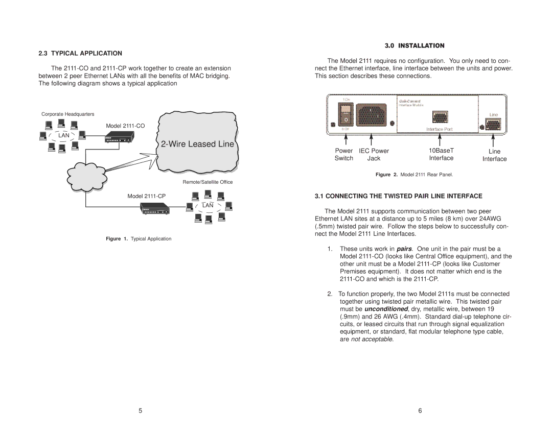
Power | IEC Power | 10BaseT | Line |
Switch | Jack | Interface | Interface |
| Figure | 2. Model 2111 Rear Panel. |
|
3.1 CONNECTING THE TWISTED PAIR LINE INTERFACE
The Model 2111 supports communication between two peer
Ethernet LAN sites at a distance up to 5 miles (8 km) over 24AWG (.5mm) twisted pair wire. Follow the steps below to successfully con- nect the Model 2111 Line Interfaces.
1.These units work in pairs. One unit in the pair must be a Model
2.To function properly, the two Model 2111s must be connected together using twisted pair metallic wire. This twisted pair must be unconditioned, dry, metallic wire, between 19 (.9mm) and 26 AWG (.4mm). Standard
5 | 6 |