1.3 Models with internal DC power supply
1.Strip insulation
2.Connect the ground terminal from the power source to the ground terminal on the IPLink.
3.Connect the negative
4.Connect the positive (+) terminal from the power source with to the positive (+) terminal on the IPLink.
1.4 Power-up indication
The Power LED blinks as the IPLink is powering up. When the Power LED stops blinking and remains lit, the IPLink is ready for you to configure.
2.0 Configure the IP address
The IPLink is shipped with a
2.1 Connecting a PC and logging in
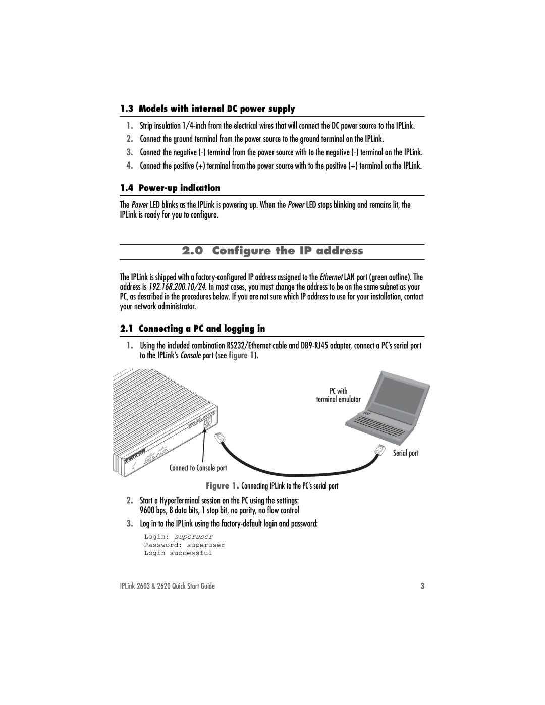
1.Using the included combination RS232/Ethernet cable and
Power
|
| Gateway |
| ipLink | Router |
2603 | Access | |
WAN |
|
|
ModelSpeed | Console | |
High | ||
|
|
|
| 100M | Rx |
|
|
| Link | Tx |
|
|
| RD |
|
| |
| Frame | Ethernet |
| ||
Link | TD |
|
|
|
|
WAN |
|
|
|
| |
|
|
|
|
| |
Connect to Console port
PC with
terminal emulator
Serial port
Figure 1. Connecting IPLink to the PC’s serial port
2.Start a HyperTerminal session on the PC using the settings:
9600 bps, 8 data bits, 1 stop bit, no parity, no flow control
3.Log in to the IPLink using the
Login: superuser
Password: superuser
Login successful
IPLink 2603 & 2620 Quick Start Guide | 3 |
