5.3 LED STATUS MONITORS
The Model IM1/I4 features two LEDs that monitor general operat- ing status and the
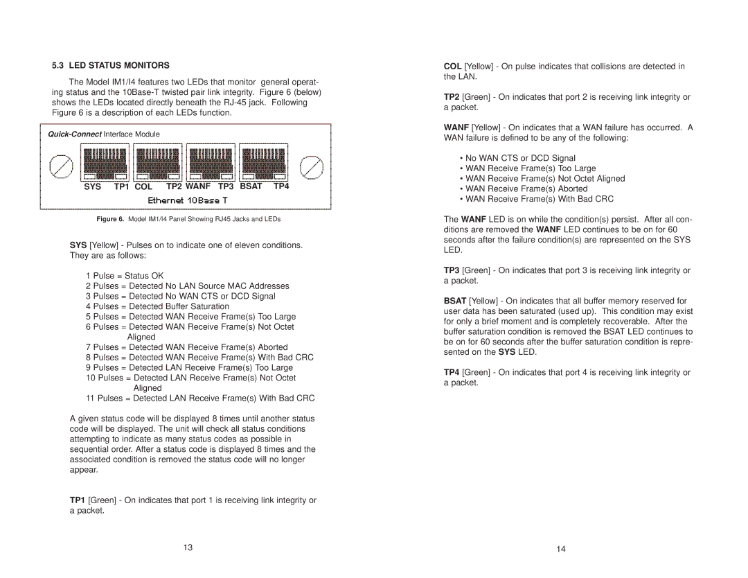
SYS TP1 COL TP2 WANF TP3 BSAT TP4
Figure 6. Model IM1/I4 Panel Showing RJ45 Jacks and LEDs
SYS [Yellow] - Pulses on to indicate one of eleven conditions. They are as follows:
1 Pulse = Status OK
2 Pulses = Detected No LAN Source MAC Addresses 3 Pulses = Detected No WAN CTS or DCD Signal
4 Pulses = Detected Buffer Saturation
5 Pulses = Detected WAN Receive Frame(s) Too Large
6 Pulses = Detected WAN Receive Frame(s) Not Octet Aligned
7 Pulses = Detected WAN Receive Frame(s) Aborted
8 Pulses = Detected WAN Receive Frame(s) With Bad CRC 9 Pulses = Detected LAN Receive Frame(s) Too Large
10 Pulses = Detected LAN Receive Frame(s) Not Octet Aligned
11 Pulses = Detected LAN Receive Frame(s) With Bad CRC
A given status code will be displayed 8 times until another status code will be displayed. The unit will check all status conditions attempting to indicate as many status codes as possible in sequential order. After a status code is displayed 8 times and the associated condition is removed the status code will no longer appear.
TP1 [Green] - On indicates that port 1 is receiving link integrity or a packet.
COL [Yellow] - On pulse indicates that collisions are detected in the LAN.
TP2 [Green] - On indicates that port 2 is receiving link integrity or a packet.
WANF [Yellow] - On indicates that a WAN failure has occurred. A WAN failure is defined to be any of the following:
•No WAN CTS or DCD Signal
•WAN Receive Frame(s) Too Large
•WAN Receive Frame(s) Not Octet Aligned
•WAN Receive Frame(s) Aborted
•WAN Receive Frame(s) With Bad CRC
The WANF LED is on while the condition(s) persist. After all con- ditions are removed the WANF LED continues to be on for 60 seconds after the failure condition(s) are represented on the SYS LED.
TP3 [Green] - On indicates that port 3 is receiving link integrity or a packet.
BSAT [Yellow] - On indicates that all buffer memory reserved for user data has been saturated (used up). This condition may exist for only a brief moment and is completely recoverable. After the buffer saturation condition is removed the BSAT LED continues to be on for 60 seconds after the buffer saturation condition is repre- sented on the SYS LED.
TP4 [Green] - On indicates that port 4 is receiving link integrity or a packet.
13 | 14 |