3.0 CONFIGURATION
The Model IM1/14 module plugs into Patton’s fiber and copper baseband modems to provide Ethernet LAN extension. The IM1/14 has no switches or jumpers and does not need to be configured.
However, factors such as type of medium, throughput across the link and clocking mode must be determined by the settings of the base- band modems. Please refer to your baseband modem (i.e. 1092A, 1095, etc) to make the following settings.
1)Bit Rate: The DTE rate setting of your base unit corresponds to the throughput of your IM1/14 bridge module. Use higher speeds to allow maximum throughput to your extended LAN.
NOTE: The IM1/14 only supports synchronous speeds.
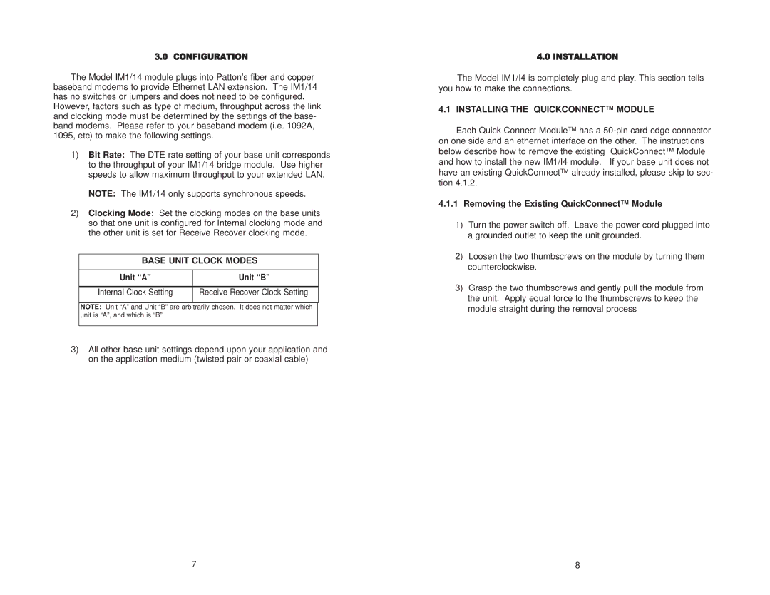
2)Clocking Mode: Set the clocking modes on the base units so that one unit is configured for Internal clocking mode and the other unit is set for Receive Recover clocking mode.
BASE UNIT CLOCK MODES
Unit “A” | Unit “B” |
|
|
Internal Clock Setting | Receive Recover Clock Setting |
|
|
NOTE: Unit “A” and Unit “B” are arbitrarily chosen. It does not matter which unit is “A”, and which is “B”.
3)All other base unit settings depend upon your application and on the application medium (twisted pair or coaxial cable)
4.0 INSTALLATION
The Model IM1/I4 is completely plug and play. This section tells you how to make the connections.
4.1 INSTALLING THE QUICKCONNECT™ MODULE
Each Quick Connect Module™ has a
4.1.1Removing the Existing QuickConnect™ Module
1)Turn the power switch off. Leave the power cord plugged into a grounded outlet to keep the unit grounded.
2)Loosen the two thumbscrews on the module by turning them counterclockwise.
3)Grasp the two thumbscrews and gently pull the module from the unit. Apply equal force to the thumbscrews to keep the module straight during the removal process
7 | 8 |
