5.0 OPERATION
When the Model 2707 has been properly configured and installed, it should operate transparently. This sections describes
5.1 POWER-UP
Before applying power to the Model 2707, please read section 4.3, “Power Connection” on page 11 and ensure that the unit is properly connected to the appropriate power source.
5.2 LED STATUS MONITORS
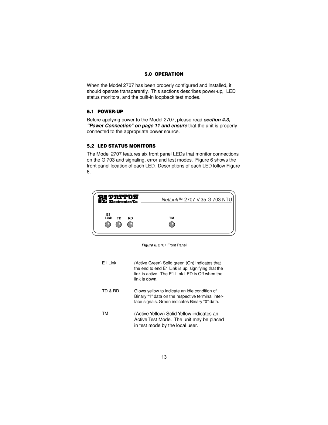
The Model 2707 features six front panel LEDs that monitor connections on the G.703 and signaling, error and test modes. Figure 6 shows the front panel location of each LED. Descriptions of each LED follow Figure 6.
| Figure 6. 2707 Front Panel |
E1 Link | (Active Green) Solid green (On) indicates that |
| the end to end E1 Link is up, signifying that the |
| link is active. The E1 Link LED is Off when the |
| link is down. |
TD & RD | Glows yellow to indicate an idle condition of |
| Binary “1” data on the respective terminal inter- |
| face signals. Green indicates Binary “0” data. |
TM | (Active Yellow) Solid Yellow indicates an |
| Active Test Mode. The unit may be placed |
| in test mode by the local user. |
13