12 D specifications
The Peavey 12 D is a versatile and powerful loudspeaker designed to meet the demands of live sound reinforcement and various audio applications. Known for its high performance and reliability, the 12 D is aimed at musicians, DJs, and sound engineers who require quality sound and durability in a portable package.One of the key features of the Peavey 12 D is its impressive power handling capability. The loudspeaker can handle up to 300 watts of continuous power and peaks at 1200 watts, making it suitable for medium to large venues. This robust power handling allows the speaker to reproduce audio with clarity and impact, ensuring that every note and vocal cut through the mix.
The 12 D employs a 12-inch heavy-duty woofer that provides deep, resonant bass response, ideal for a range of music genres. This is complemented by a high-frequency driver that delivers crystal-clear treble frequencies, allowing for a balanced sound profile. The combination of these components results in a full-range sound that is both vibrant and articulate.
Incorporating advanced technologies, the Peavey 12 D features a constant directivity horn that offers controlled dispersion of sound. This ensures consistent coverage across the audience area, minimizing dead spots and providing an even listening experience. Additionally, the speaker is equipped with Peavey's proprietary EQ settings, allowing users to tailor the sound output to their specific environment or preferences.
Portability and ease of use are also central to the design of the Peavey 12 D. Weighing in at a manageable size and featuring durable enclosures, the speaker is easy to transport and set up. Integrated handles make it convenient for mobile applications, and its rugged construction ensures it can withstand the rigors of touring.
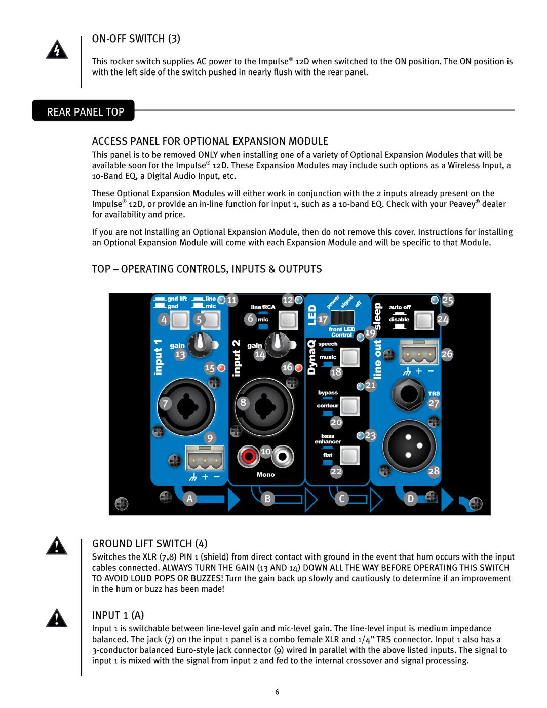
For connectivity, the Peavey 12 D offers versatile input options, allowing for seamless integration into existing sound systems. With all these characteristics combined, the Peavey 12 D stands out as a reliable and powerful choice for anyone looking to elevate their sound experience, whether on stage or at an event. Its combination of performance, technology, and user-friendly features makes it an excellent option for both professionals and enthusiasts alike.

