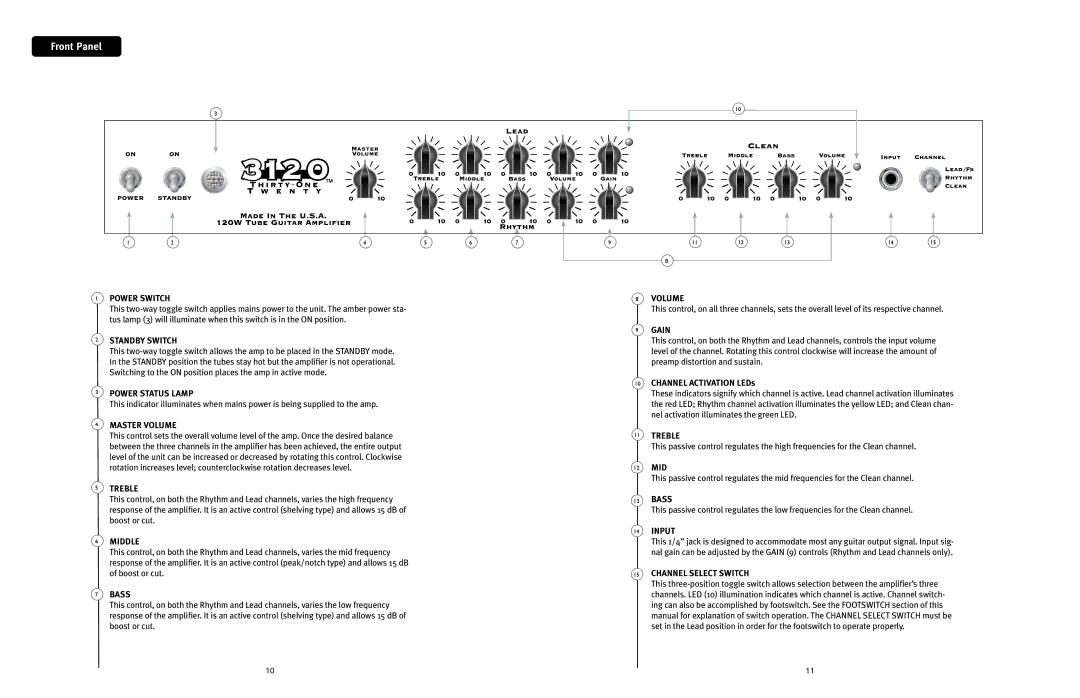
Front Panel
|
| 3 |
|
|
|
|
| 10 |
|
|
|
|
|
|
|
|
|
|
|
|
|
| |
1 | 2 | 4 | 5 | 6 | 7 | 9 | 11 | 12 | 13 | 14 | 15 |
|
|
|
|
|
|
| 8 |
|
|
|
|
1
2
3
4
5
6
7
POWER SWITCH
This
STANDBY SWITCH
This
POWER STATUS LAMP
This indicator illuminates when mains power is being supplied to the amp.
MASTER VOLUME
This control sets the overall volume level of the amp. Once the desired balance between the three channels in the amplifier has been achieved, the entire output level of the unit can be increased or decreased by rotating this control. Clockwise rotation increases level; counterclockwise rotation decreases level.
TREBLE
This control, on both the Rhythm and Lead channels, varies the high frequency response of the amplifier. It is an active control (shelving type) and allows 15 dB of boost or cut.
MIDDLE
This control, on both the Rhythm and Lead channels, varies the mid frequency response of the amplifier. It is an active control (peak/notch type) and allows 15 dB of boost or cut.
BASS
This control, on both the Rhythm and Lead channels, varies the low frequency response of the amplifier. It is an active control (shelving type) and allows 15 dB of boost or cut.
8VOLUME
This control, on all three channels, sets the overall level of its respective channel.
9GAIN
This control, on both the Rhythm and Lead channels, controls the input volume level of the channel. Rotating this control clockwise will increase the amount of preamp distortion and sustain.
10CHANNEL ACTIVATION LEDs
These indicators signify which channel is active. Lead channel activation illuminates the red LED; Rhythm channel activation illuminates the yellow LED; and Clean chan- nel activation illuminates the green LED.
11TREBLE
This passive control regulates the high frequencies for the Clean channel.
12MID
This passive control regulates the mid frequencies for the Clean channel.
13BASS
This passive control regulates the low frequencies for the Clean channel.
14INPUT
This 1/4” jack is designed to accommodate most any guitar output signal. Input sig- nal gain can be adjusted by the GAIN (9) controls (Rhythm and Lead channels only).
15CHANNEL SELECT SWITCH
This
10
11
