450 specifications
The Peavey 450 is a versatile and powerful bass amplifier head designed for both amateur and professional musicians. Known for its exceptional sound quality and robust construction, this amplifier has found a place in various music genres, from rock to jazz. Its lightweight yet durable design offers musicians the portability they crave without sacrificing performance.One of the standout features of the Peavey 450 is its impressive power rating. With a capability of delivering up to 450 watts at 4 ohms, it provides ample headroom for dynamic playing. This ensures that bassists can maintain clarity and punch even at higher volumes, making it an ideal choice for live performances. The amp can also operate at lower impedances for additional power, providing flexibility for players with various cabinet setups.
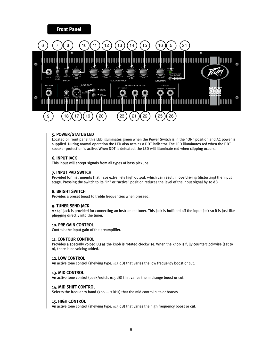
The tonal versatility of the Peavey 450 sets it apart from other amplifiers in its class. The amp incorporates a 5-band EQ, allowing musicians to finely tune their sound to match their style or the venue's acoustics. Additionally, it features Peavey's exclusive Psycho-Acoustic low-end enhancement circuitry, which enriches the bass response without overshadowing mid and high frequencies. This technology is especially beneficial for genres that demand a tight low-end punch, such as metal or funk.
Another highlight of the Peavey 450 is its built-in effects loop, which allows players to integrate their favorite pedals seamlessly into the signal chain without losing tone integrity. The amplifier also includes a balanced XLR output for direct connection to a mixer or recording device, making it convenient for studio work or live sound applications.
Durability is a hallmark of Peavey products, and the 450 is no exception. Housed in a rugged chassis, this amplifier is built to withstand the rigors of gigging. The high-quality components used in its construction ensure longevity, making it a reliable choice for touring musicians.
In summary, the Peavey 450 is a powerful and versatile amplifier that offers bassists a range of features to enhance their sound and performance. With its robust power, advanced EQ capabilities, and durable design, it stands out as a reliable choice for musicians looking to elevate their sound. Whether on stage or in the studio, the Peavey 450 helps bassists achieve their desired tone with ease and clarity.

