7/8. EFFECTS SEND/EFFECTS RETURN
Signals are supplied to outboard effects or signal processing units by patching from the Effects Send (7) output into the outboard unit(s) and back into the Effects Return (8) input using shielded cables with 1/4" mono phone plugs. Only
9. PREAMP OUT
This output can be used to send a preamp signal from the 6505™+ to a mixing console, tape recorder, etc., using a shielded instrument cable. Patching from the PREAMP OUT does not affect the normal operation of the amplifier.
BIAS ADJUST SYSTEM
10. BIAS TEST TERMINALS
These terminals, along with the adjustment knob behind the grille are provided to measure and adjust the power amp tubes’ bias. The bias adjustment should only be done by a qualified technician.
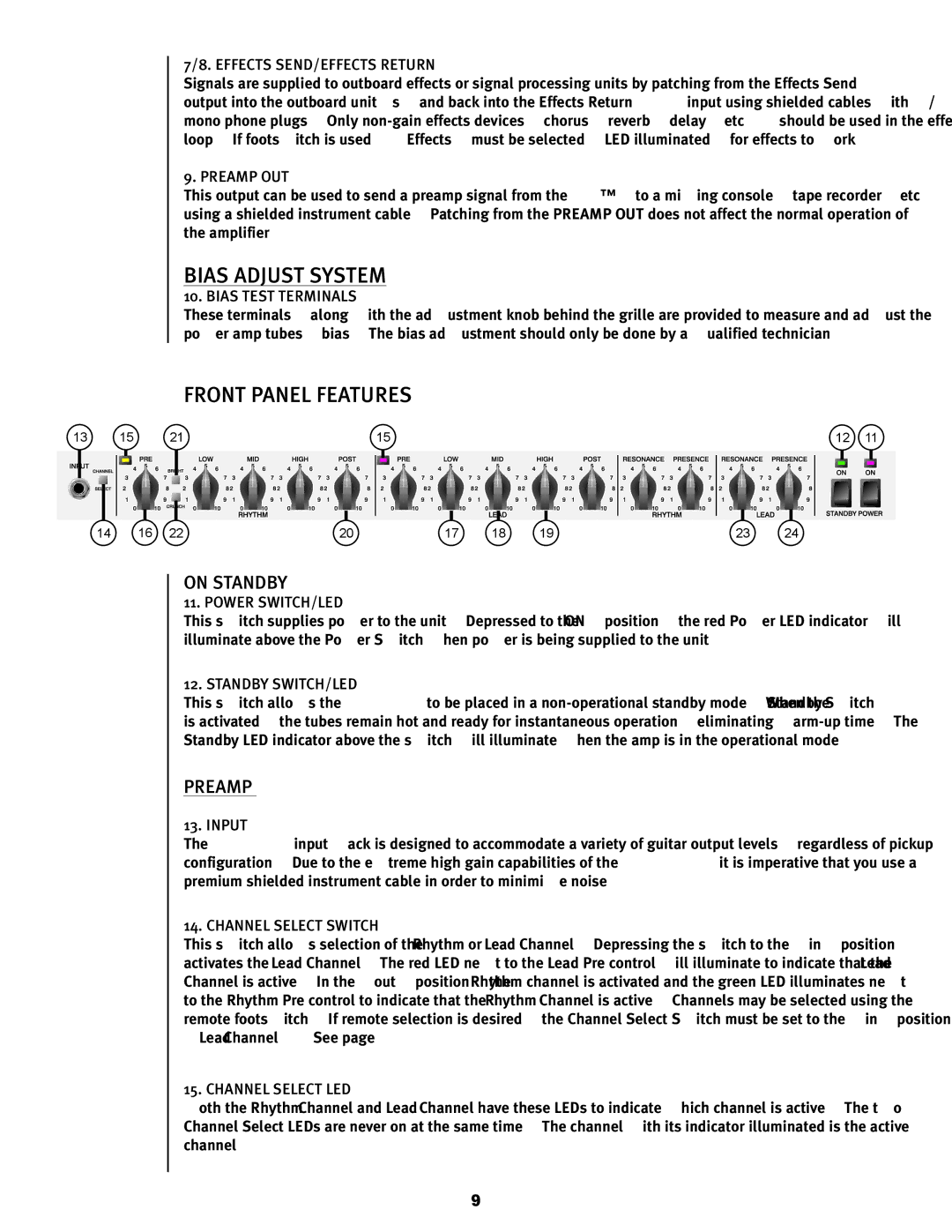
FRONT PANEL FEATURES
13 | 15 | 21 | 15 | 12 | 11 |
14 | 16 | 22 | 20 | 17 | 18 | 19 | 23 | 24 |
ON STANDBY
11. POWER SWITCH/LED
This switch supplies power to the unit. Depressed to the “ON” position, the red Power LED indicator will illuminate above the Power Switch when power is being supplied to the unit.
12. STANDBY SWITCH/LED
This switch allows the 6505+ to be placed in a
PREAMP
13. INPUT
The 6505+ input jack is designed to accommodate a variety of guitar output levels, regardless of pickup configuration. Due to the extreme high gain capabilities of the 6505+, it is imperative that you use a premium shielded instrument cable in order to minimize noise.
14. CHANNEL SELECT SWITCH
This switch allows selection of the Rhythm or Lead Channel. Depressing the switch to the “in” position activates the Lead Channel. The red LED next to the Lead Pre control will illuminate to indicate that the Lead Channel is active. In the “out” position, the Rhythm channel is activated and the green LED illuminates next to the Rhythm Pre control to indicate that the Rhythm Channel is active. Channels may be selected using the remote footswitch. If remote selection is desired, the Channel Select Switch must be set to the “in” position (Lead Channel). See page 11.
15. CHANNEL SELECT LED
Both the Rhythm Channel and Lead Channel have these LEDs to indicate which channel is active. The two Channel Select LEDs are never on at the same time. The channel with its indicator illuminated is the active channel.
9