Front Panel
STEREO INPUT CHANNELS
14Mic Gain
This control establishes the nominal operating level for the mic input (XLR) of the channel. The mic gain can be adjusted over a wide range (0 dB – 60 dB) to compensate for soft voices or very loud drums. To maximize the
15Stereo Gain
This control establishes the nominal operating level for the stereo line inputs (1/4" jacks) of the channel. The Stereo Gain can be adjusted over a sufficient range
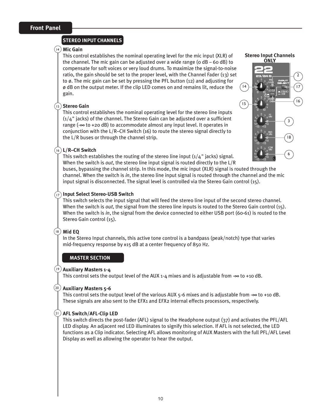
Stereo Input Channels
ONLY
| 2 |
14 | 17 |
15 | 16 |
|
3
18
16 | 6 | |
This switch establishes the routing of the stereo line input (1/4" jacks) signal. | ||
| ||
When the switch is out, the stereo line input signal is routed directly to the L/R |
| |
buses, bypassing the channel strip. In this mode, the mic input (XLR) signal is routed through the |
| |
channel. When the switch is in, the stereo line input signal is routed through the channel and the mic |
| |
input signal is disconnected. The signal level is controlled via the Stereo Gain control (15). |
|
17Input Select Stereo-USB Switch
This switch selects the input signal that will feed the stereo line input of the second stereo channel. When the switch is out, the signal from the stereo line inputs is routed to the Stereo Gain control (15). When the switch is in, the signal from the device connected to either USB port
18Mid EQ
In the Stereo Input channels, this active tone control is a bandpass (peak/notch) type that varies
MASTER SECTION
19Auxiliary Masters 1-4
This control sets the output level of the AUX
20Auxiliary Masters
This control sets the output level of the various AUX
21AFL Switch/AFL-Clip LED
This switch directs the
10