Front Panel
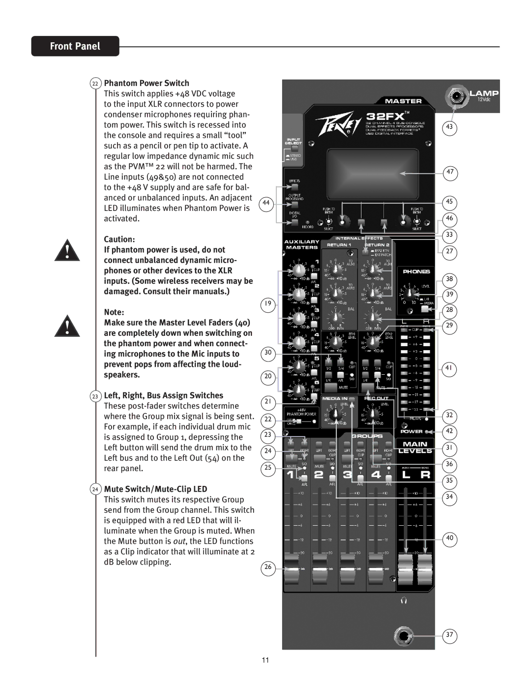
22Phantom Power Switch
This switch applies +48 VDC voltage to the input XLR connectors to power condenser microphones requiring phan- tom power. This switch is recessed into the console and requires a small “tool” such as a pencil or pen tip to activate. A regular low impedance dynamic mic such as the PVM™ 22 will not be harmed. The Line inputs (49&50) are not connected to the +48 V supply and are safe for bal- anced or unbalanced inputs. An adjacent LED illuminates when Phantom Power is activated.
Caution:
If phantom power is used, do not connect unbalanced dynamic micro- phones or other devices to the XLR inputs. (Some wireless receivers may be damaged. Consult their manuals.)
Note:
Make sure the Master Level Faders (40) are completely down when switching on the phantom power and when connect- ing microphones to the Mic inputs to prevent pops from affecting the loud- speakers.
23Left, Right, Bus Assign Switches These
24Mute Switch/Mute-Clip LED
This switch mutes its respective Group send from the Group channel. This switch is equipped with a red LED that will il- luminate when the Group is muted. When the Mute button is out, the LED functions as a Clip indicator that will illuminate at 2 dB below clipping.
44
19
30
20
21
22
23
24
25
26
43
47
45
46
33
27
38
39
28
29
41
32 |
42 |
31 |
36 |
35 |
34 |
40
37
11