Front Panel
25Phantom Power Switch
This Switch applies +48 VDC voltage to the input XLR connectors to power microphones requiring phan- tom power.
If phantom power is used, do not connect unbalanced dynamic microphones or other devices to the XLR inputs.
26Tape To CTRL/HP
Depressing this switch adds the tape return to the Control Room (39) and Headphone Outputs (41) for zero latency monitoring.
27Tape/to Mix (Tape/USB to Mix)
Depressing this switch routes the signal from the Tape Inputs (13) or USB Input (44) to the Left/Right Outputs (40). The USB input level is controlled by the computer volume control.
28Tape/USB to Main (PV™20 only)
This knob provides a convenient way to adjust the Tape Input (13) or USB Input (44) volume. (On models PV™10 and PV™14, adjust the USB Input (44) volume with the computer volume control.)
29Contour Switch
Engaging this switch enhances the signal by adding both bass and treble frequencies. This is especially effective at lower volumes or for tape/CD playback.
30Master Level Faders
These Master Faders control the levels sent to the main left/right outputs. Best results are obtained when these controls are set near the 0 point.
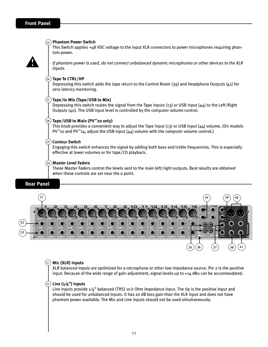
Rear Panel
|
| 31 |
|
|
|
|
|
|
|
|
|
|
|
|
|
|
|
| 34 |
|
|
| 39 | 40 |
|
| 1 | 2 | 3 | 4 | 5 | 6 | 7 | 8 | 9 10 | 11 12 13 14 15 | 16 | 17 18 | 19 20 |
|
|
| |||||||
|
|
|
|
|
|
|
|
|
|
|
|
|
|
|
|
|
| L/ | A | L / | A | L |
|
|
|
|
|
|
|
|
|
|
|
|
|
|
|
|
|
|
|
| MONO | MONO | CTRL/ROOM |
|
| ||
|
| MIC | MIC | MIC | MIC | MIC | MIC | MIC | MIC | MIC | MIC | MIC | MIC | MIC | MIC | MIC | MIC | R |
| R |
| R | LEFT OUT | RIGHT OUT |
32 |
| BAL | BAL | BAL | BAL | BAL | BAL | BAL | BAL | BAL | BAL | BAL | BAL | BAL | BAL | BAL | BAL |
|
|
|
|
|
|
|
|
|
|
|
|
|
|
|
|
|
|
|
|
|
|
|
|
| L |
| L |
|
| OUTPUTS | |
|
|
|
|
|
|
|
|
|
|
|
|
|
|
|
|
|
|
|
|
|
| |||
| INPUTS | LINE | LINE | LINE | LINE | LINE | LINE | LINE | LINE | LINE | LINE | LINE | LINE | LINE | LINE | LINE | LINE |
| B |
| B | MON 1 SEND |
| |
|
|
|
|
|
|
|
|
|
|
|
|
|
|
|
|
|
|
|
|
|
| |||
33 |
|
|
|
|
|
|
|
|
|
|
|
|
|
|
|
|
| R |
| R |
|
| ||
|
|
|
|
|
|
|
|
|
|
|
|
|
|
|
| A |
|
| A |
|
| |||
|
|
|
|
|
|
|
|
|
|
|
|
|
|
|
| B | A/B | A/B | B |
|
| |||
|
|
|
|
|
|
|
|
|
|
|
|
|
|
|
|
|
|
|
|
|
|
| ||
|
| INSERT | INSERT | INSERT | INSERT | INSERT | INSERT | INSERT | INSERT | INSERT | INSERT | INSERT | INSERT | INSERT | INSERT | INSERT | INSERT |
| INPUT | INPUT | MON 2 SEND | EFX SEND |
| |
|
|
|
|
|
|
|
|
| ||||||||||||||||
|
|
|
|
|
|
|
|
|
|
|
|
|
|
|
|
| 35 | 36 |
|
| 37 |
| 38 | 41 |
31
Mic (XLR) Inputs
XLR balanced inputs are optimized for a microphone or other low impedance source. Pin 2 is the positive input. Because of the wide range of gain adjustment, signal levels up to +14 dBu can be accommodated.
32Line (1⁄4”) Inputs
Line inputs provide 1⁄4” balanced (TRS) 10 k Ohm impedance input. The tip is the positive input and should be used for unbalanced inputs. It has 20 dB less gain than the XLR input and does not have phantom power available. The Mic and Line inputs should not be used simultaneously.
11