Front Panel
16EFX Time
This control adjusts the time of the particular reverb or delay.
17Green Signal LED and Red Clip LED
The green Signal LED and red Clip LED are used to set the operating input level to the PV™10, PV™14, and PV™20 effects processors. The signal level to the processor is affected by channel Fader, the Effects Send and the Effects Send Master Controls. Start with the Master Control (20) set to 0 (12 o’clock) and adjust the channel sends so that the signal LED lights and the clip LED blinks on occasionally, if at all. The clip LED lights 6 dB below clipping. Pressing the EFX defeat mutes the effects signal and lights the clip/mute LED.
18EFX Return
Once the input level is set (see 17) use the EFX Return control to mix the effects processor output into the main left/right outputs. Remember, a little reverb goes a long way.
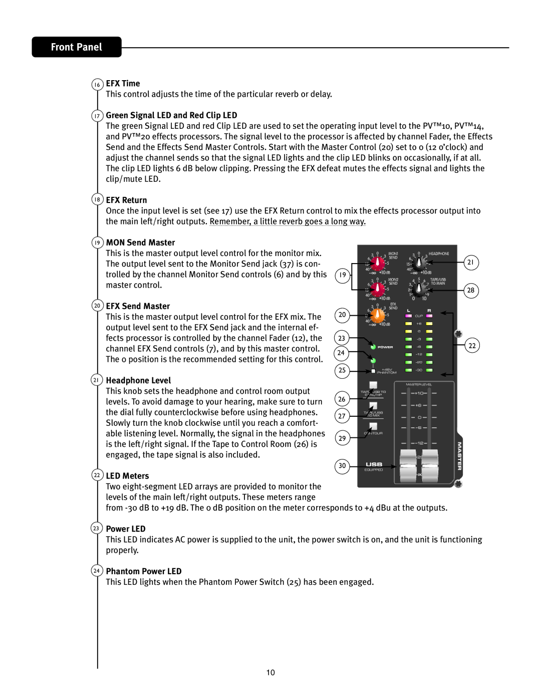
19MON Send Master
This is the master output level control for the monitor mix. The output level sent to the Monitor Send jack (37) is con- trolled by the channel Monitor Send controls (6) and by this master control.
20EFX Send Master
This is the master output level control for the EFX mix. The output level sent to the EFX Send jack and the internal ef- fects processor is controlled by the channel Fader (12), the channel EFX Send controls (7), and by this master control. The 0 position is the recommended setting for this control.
19
20
23
24
25
3 | 0 | 3 | MON1 |
6 |
| SEND |
15![]()
![]() 5
5
40
![]() 10dB
10dB
3 | 0 | 3 | MON2 |
6 |
| SEND |
15![]()
![]() 5
5
40
![]() 10dB
10dB
0EFX
6 3![]()
![]()
![]() 3 SEND
3 SEND
15![]()
![]() 5
5
40 | 10dB |
|
![]() POWER
POWER
+48V
PHANTOM
3 | 0 | 3 | HEADPHONE | ||
6 |
|
|
|
| |
|
|
|
|
| |
15 |
|
| 5 |
|
|
40 |
| 10dB | |||
|
| ||||
4 | 5 | 6 |
| TAPE/USB | |
3 |
| 7 | TO MAIN | ||
2 |
|
| 8 |
|
|
|
|
|
| ||
1 0 |
| 10 9 |
|
| |
LR
![]() CLIP
CLIP ![]()
+6
0
21
28
22
21 | Headphone Level |
|
|
|
|
|
|
|
|
|
|
| MASTER LEVEL |
|
|
|
|
|
|
|
|
|
|
| |||
| This knob sets the headphone and control room output |
|
|
|
|
|
|
|
|
|
| 10 | |
|
|
|
|
|
| CTRL/HP | |||||||
|
|
|
|
|
| TAPE/USB TO |
| ||||||
| levels. To avoid damage to your hearing‚ make sure to turn | 26 |
|
|
|
|
|
|
|
|
|
| 6 |
|
|
|
|
|
|
|
|
| |||||
|
|
|
|
|
|
|
|
|
|
|
| ||
| the dial fully counterclockwise before using headphones. |
|
|
|
|
|
|
| TO MIX |
| |||
|
| 27 |
|
|
|
| TAPE/USB |
| |||||
| Slowly turn the knob clockwise until you reach a comfort- |
|
|
|
|
|
|
|
|
|
| 0 | |
|
|
|
|
|
|
|
|
|
|
|
| 6 | |
|
|
|
|
|
|
|
|
|
|
|
| ||
| able listening level. Normally, the signal in the headphones | 29 |
|
|
|
| CONTOUR |
| |||||
| is the left/right signal. If the Tape to Control Room (26) is |
|
|
|
|
|
|
|
|
|
| 12 | |
|
|
|
|
|
|
|
|
|
|
| |||
|
|
|
|
|
|
|
|
|
|
|
| ||
| engaged‚ the tape signal is also included. |
|
|
|
|
|
|
|
|
|
|
| 20 |
|
| 30 |
|
|
|
|
| USB |
| ||||
| LED Meters |
| EQUIPPED |
| |||||||||
|
|
|
|
|
|
| |||||||
22 |
|
|
|
|
|
|
|
|
|
|
|
| |
| Two |
|
|
|
|
|
|
|
|
|
|
|
|
| levels of the main left/right outputs. These meters range |
|
|
|
|
|
|
|
|
|
|
|
|
| from | ||||||||||||
MASTER
23Power LED
This LED indicates AC power is supplied to the unit‚ the power switch is on, and the unit is functioning properly.
24Phantom Power LED
This LED lights when the Phantom Power Switch (25) has been engaged.
10