Connections
1.Connect video output.
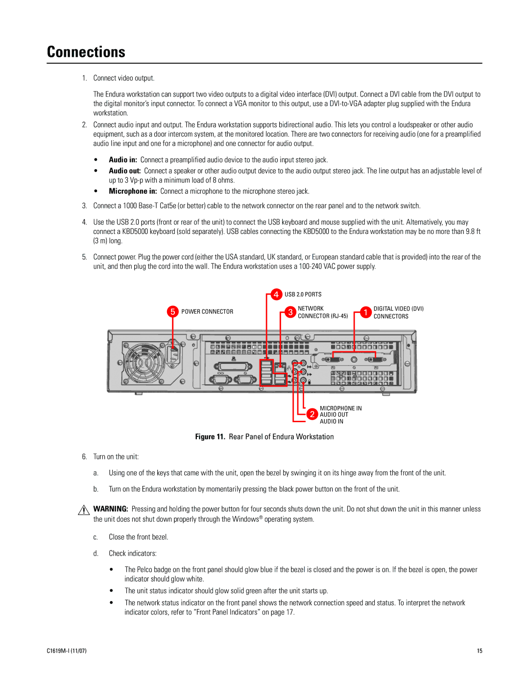
The Endura workstation can support two video outputs to a digital video interface (DVI) output. Connect a DVI cable from the DVI output to the digital monitor’s input connector. To connect a VGA monitor to this output, use a
2.Connect audio input and output. The Endura workstation supports bidirectional audio. This lets you control a loudspeaker or other audio equipment, such as a door intercom system, at the monitored location. There are two connectors for receiving audio (one for a preamplified audio line input and one for a microphone) and one connector for audio output.
•Audio in: Connect a preamplified audio device to the audio input stereo jack.
•Audio out: Connect a speaker or other audio output device to the audio output stereo jack. The line output has an adjustable level of up to 3
•Microphone in: Connect a microphone to the microphone stereo jack.
3.Connect a 1000
4.Use the USB 2.0 ports (front or rear of the unit) to connect the USB keyboard and mouse supplied with the unit. Alternatively, you may connect a KBD5000 keyboard (sold separately). USB cables connecting the KBD5000 to the Endura workstation may be no more than 9.8 ft (3 m) long.
5.Connect power. Plug the power cord (either the USA standard, UK standard, or European standard cable that is provided) into the rear of the unit, and then plug the cord into the wall. The Endura workstation uses a
![]() POWER CONNECTOR
POWER CONNECTOR
![]() USB 2.0 PORTS
USB 2.0 PORTS
NETWORK
CONNECTOR
DIGITAL VIDEO (DVI) CONNECTORS
MICROPHONE IN
AUDIO OUT
AUDIO IN
Figure 11. Rear Panel of Endura Workstation
6.Turn on the unit:
a.Using one of the keys that came with the unit, open the bezel by swinging it on its hinge away from the front of the unit.
b.Turn on the Endura workstation by momentarily pressing the black power button on the front of the unit.
WARNING: Pressing and holding the power button for four seconds shuts down the unit. Do not shut down the unit in this manner unless the unit does not shut down properly through the Windows® operating system.
c.Close the front bezel.
d.Check indicators:
•The Pelco badge on the front panel should glow blue if the bezel is closed and the power is on. If the bezel is open, the power indicator should glow white.
•The unit status indicator should glow solid green after the unit starts up.
•The network status indicator on the front panel shows the network connection speed and status. To interpret the network indicator colors, refer to “Front Panel Indicators” on page 17.
15 |
