Pelco C2624M manual Connections

Models: C2624M

1 36
Download 36 pages 11.88 Kb
Page 18
Image 18

CONNECTIONS

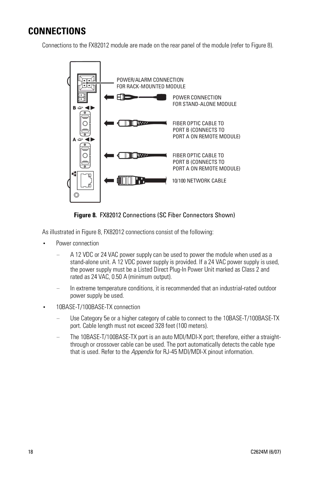
Connections to the FX82012 module are made on the rear panel of the module (refer to Figure 8).

POWER/ALARM CONNECTION

FOR RACK-MOUNTED MODULE

POWER CONNECTION

FOR STAND-ALONE MODULE

FIBER OPTIC CABLE TO

PORT B (CONNECTS TO

PORT A ON REMOTE MODULE)

FIBER OPTIC CABLE TO

PORT B (CONNECTS TO

PORT A ON REMOTE MODULE)

10/100 NETWORK CABLE

Figure 8. FX82012 Connections (SC Fiber Connectors Shown)

As illustrated in Figure 8, FX82012 connections consist of the following:

Power connection

A 12 VDC or 24 VAC power supply can be used to power the module when used as a stand-alone unit. A 12 VDC power supply is provided. If a 24 VAC power supply is used, the power supply must be a Listed Direct Plug-In Power Unit marked as Class 2 and rated as 24 VAC, 0.50 A (minimum output).

In extreme temperature conditions, it is recommended that an industrial-rated outdoor power supply be used.

10BASE-T/100BASE-TX connection

Use Category 5e or a higher category of cable to connect to the 10BASE-T/100BASE-TX port. Cable length must not exceed 328 feet (100 meters).

The 10BASE-T/100BASE-TX port is an auto MDI/MDI-X port; therefore, either a straight- through or crossover cable can be used. The port automatically detects the cable type that is used. Refer to the Appendix for RJ-45 MDI/MDI-X pinout information.

18

C2624M (6/07)

Page 18
Image 18
Pelco C2624M manual Connections