![]() WARNING: Do not connect the included PV140 power supply. The PV140 receives power from the computer and does not need a separate power supply.
WARNING: Do not connect the included PV140 power supply. The PV140 receives power from the computer and does not need a separate power supply.
Computer: The computer on which DS ControlPoint is running.
KBD300A Keyboard: Controls PTZ cameras connected to the computer. A
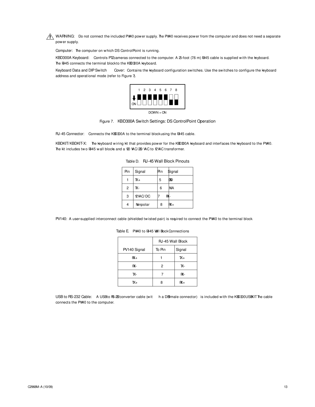
Keyboard Data and DIP Switch Cover: Contains the keyboard configuration switches. Use the switches to configure the keyboard address and operational mode (refer to Figure 7).
1 2 3 4 5 6 7 8
ON ![]()
DOWN = ON
Figure 7. KBD300A Switch Settings: DS ControlPoint Operation
RJ-45 Connector: Connects the KBD300A to the terminal block using the RJ-45 cable.
Table D. RJ-45 Wall Block Pinouts
Pin | Signal | Pin | Signal |
|
|
|
|
1 | TX+ | 5 | GND |
|
|
|
|
2 | TX- | 6 | N/A |
|
|
|
|
3 | 12 VAC/DC | 7 | RX- |
|
|
|
|
4 | Nonpolar | 8 | RX+ |
|
|
|
|
PV140: A
Table E. PV140 to
|
| |
|
|
|
PV140 Signal | To Pin | Signal |
|
|
|
RX+ | 1 | TX+ |
|
|
|
RX- | 2 | TX- |
|
|
|
TX- | 7 | RX- |
|
|
|
TX+ | 8 | RX+ |
|
|
|
USB to
13 |