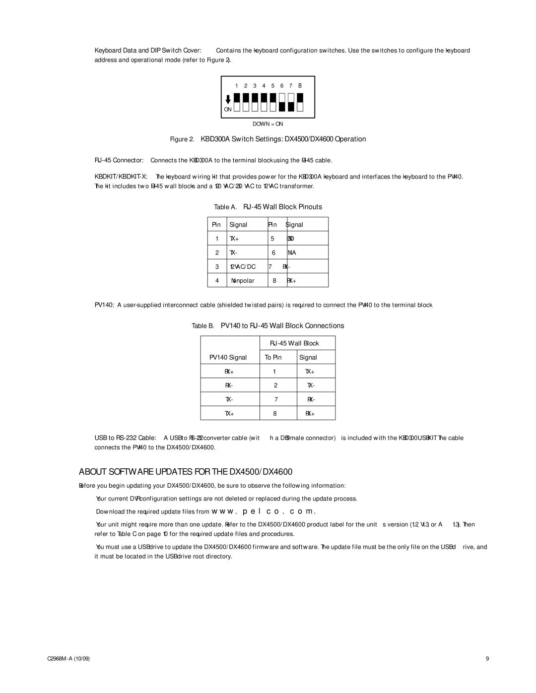
Keyboard Data and DIP Switch Cover: Contains the keyboard configuration switches. Use the switches to configure the keyboard address and operational mode (refer to Figure 2).
1 2 3 4 5 6 7 8
ON ![]()
DOWN = ON
Figure 2. KBD300A Switch Settings: DX4500/DX4600 Operation
RJ-45 Connector: Connects the KBD300A to the terminal block using the RJ-45 cable.
Table A.
Pin | Signal | Pin | Signal |
|
|
|
|
1 | TX+ | 5 | GND |
|
|
|
|
2 | TX- | 6 | N/A |
|
|
|
|
3 | 12 VAC/DC | 7 | RX- |
|
|
|
|
4 | Nonpolar | 8 | RX+ |
|
|
|
|
PV140: A
Table B. PV140 to
|
| |
|
|
|
PV140 Signal | To Pin | Signal |
|
|
|
RX+ | 1 | TX+ |
|
|
|
RX- | 2 | TX- |
|
|
|
TX- | 7 | RX- |
|
|
|
TX+ | 8 | RX+ |
|
|
|
USB to
ABOUT SOFTWARE UPDATES FOR THE DX4500/DX4600
Before you begin updating your DX4500/DX4600, be sure to observe the following information:
•Your current DVR configuration settings are not deleted or replaced during the update process.
•Download the required update files from www.pelco.com.
•Your unit might require more than one update. Refer to the DX4500/DX4600 product label for the unit’s version (1.2, V1.3, or A1.3). Then refer to Table C on page 10 for the required update files and procedures.
•You must use a USB drive to update the DX4500/DX4600 firmware and software. The update file must be the only file on the USB drive, and it must be located in the USB drive root directory.
9 |