3.3.1 Receiver Control Output for 12 VDC Camera Option
NOTE: The Coaxitron® receiver with preset positions is designed for use with preset capable Coaxitron® controllers only.
The usual output for camera power is 24 VAC, accessed at pins 9 and 14 of the 37- pin AMP connector (see Table C) where camera AC (high) and camera AC (low) emerge as camera input power.
The output pin assignments remain the same for 12 VDC camera power options. However, pin 9 is positive (+) and pin 14 is negative
3.4 COAXITRON® RECEIVER PRESETS
The Coaxitron® system uses precision linear taper potentiometers as position feed- back sensors. This feedback voltage is digitized and stored in the receiver. Preset storage is in a nonvolatile EEPROM. This assures the preset information is stored for future use.
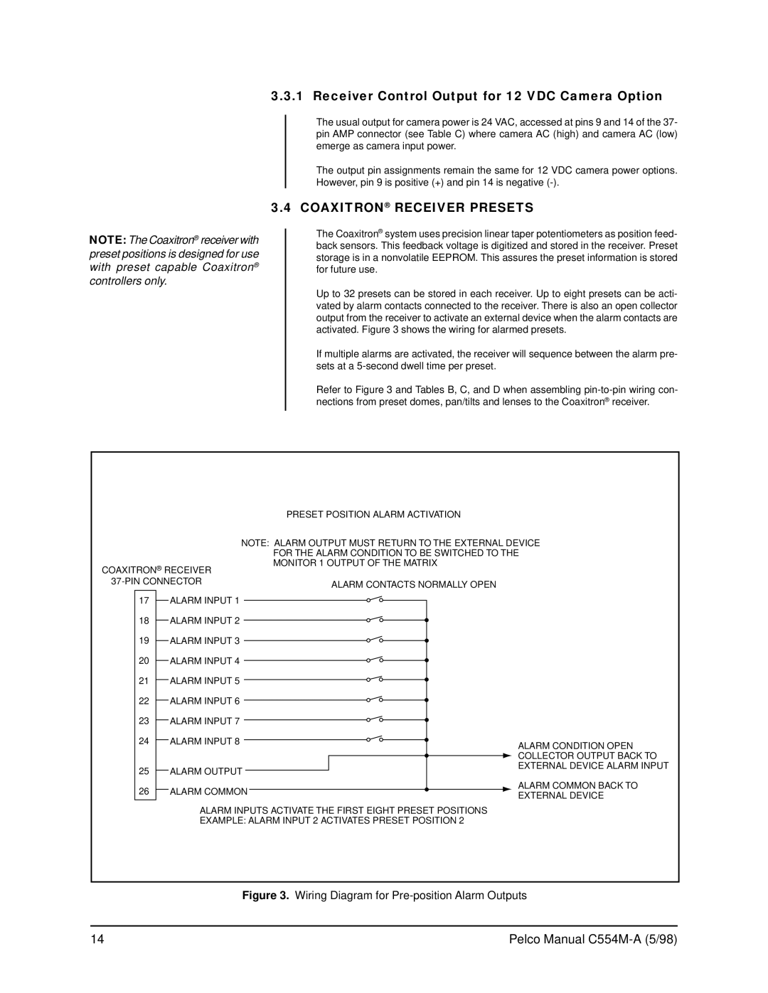
Up to 32 presets can be stored in each receiver. Up to eight presets can be acti- vated by alarm contacts connected to the receiver. There is also an open collector output from the receiver to activate an external device when the alarm contacts are activated. Figure 3 shows the wiring for alarmed presets.
If multiple alarms are activated, the receiver will sequence between the alarm pre- sets at a
Refer to Figure 3 and Tables B, C, and D when assembling
|
| PRESET POSITION ALARM ACTIVATION | |
| NOTE: ALARM OUTPUT MUST RETURN TO THE EXTERNAL DEVICE | ||
|
| FOR THE ALARM CONDITION TO BE SWITCHED TO THE | |
COAXITRON® RECEIVER | MONITOR 1 OUTPUT OF THE MATRIX | ||
| |||
ALARM CONTACTS NORMALLY OPEN | |||
|
| ||
17 | ALARM INPUT 1 |
| |
18 | ALARM INPUT 2 |
| |
19 | ALARM INPUT 3 |
| |
20 | ALARM INPUT 4 |
| |
21 | ALARM INPUT 5 |
| |
22 | ALARM INPUT 6 |
| |
23 | ALARM INPUT 7 |
| |
24 | ALARM INPUT 8 | ALARM CONDITION OPEN | |
|
| ||
|
| COLLECTOR OUTPUT BACK TO | |
25 | ALARM OUTPUT | EXTERNAL DEVICE ALARM INPUT | |
| |||
26 | ALARM COMMON | ALARM COMMON BACK TO | |
EXTERNAL DEVICE | |||
|
| ||
ALARM INPUTS ACTIVATE THE FIRST EIGHT PRESET POSITIONS
EXAMPLE: ALARM INPUT 2 ACTIVATES PRESET POSITION 2
Figure 3. Wiring Diagram for Pre-position Alarm Outputs
14 | Pelco Manual |