English

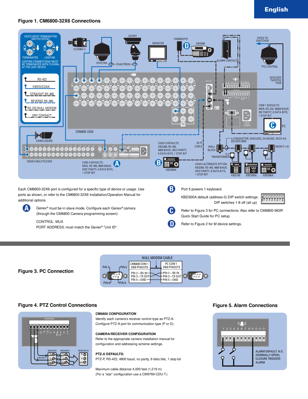
Figure 1. CM6800-32X6 Connections

VIDEO INPUT TERMINATING

SWITCH DETAIL

HZHZ

11

7575

TERMINATED LOOPING

LOOPING CONNECTIONS MUST BE TERMINATED WITH 75 OHMs

AT THE LAST DEVICE

RS-422

VIDEO/COAX

STRAIGHT RS-485

REVERSE RS-485

RS-232 NULL MODEM

DRY CONTACT


ESPRIT


CM9505UPS


VIDEO TO


SWITCHER


MONITOR


D


KBD960


CC3700H-2


SPECTRA


ALARM CONTACT


COAXITRON


PTZ CONTROL


SHIELDED


010101


TWISTED


HZ


9

10

11

12

13

14

15

16


1

2

3

4

5

6

7

8


PAIR


1

2

3

4

5

6

7

8


75


2


CONTROL


3


T

T


R R


F


+

-


-

+


2


17

18

19

20

21

22

23

24

25

26

27

28

29

30

31

32

4

OR


1

2

3

5


COM 1 DEFAULTS:


MGR, RS-232, 56000 BAUD,


1


NO PARITY, 8 DATA BITS,


4

5

6


1 STOP BIT


120/230~

C

PC


50/60 HZ


25 WATTS


CM6800-32X6

CAMCLOSURE

COM 5 DEFAULTS:

25 FT

4-CONDUCTOR, SHIELDED, 24-GAUGE, SUCH AS BELDEN 9843

SPOT MAIN

VCR

IN COM OUT N NH


O C C S

AUX

OUT

IN


ALARMS


SVHS

SVHS

1 2 3 4 5 6 7

8

9 10 111213141516

110-240V 50/60 Hz

GENEX MULTIPLEXER

COM 4 DEFAULTS:

A


MUX, RS-485, 9600 BAUD,


ODD PARITY, 8 DATA BITS,


1 STOP BIT


KBD300, RS-485

9600 BAUD, ODD PARITY,

8 DATA BITS, 1 STOP BIT

B

KBD300A

CABLE WALL KBDKIT (-X)

BLOCK 12 V

TRANSFORMER

COM 4 ALTERNATE OPTION:


KBD300, RS-485, 9600 BAUD,


ODD PARITY, 8 DATA BITS,


1 STOP BIT

KBD100

KBD200A

KBD300A

Each CM6800-32X6 port is configured for a specific type of device or usage. Use ports as shown, or refer to the CM6800-32X6 Installation/Operation Manual for additional options.

A

Genex® must be in slave mode. Configure each Genex® camera


(through the CM6800 Camera programming screen):

CONTROL: MUX

PORT ADDRESS: must match the Genex® ”Unit ID“

B

C

D

Port 5 powers 1 keyboard.

KBD300A default (address 0) DIP switch settings: DIP switches 1-8 off (all up)

Refer to Figure 3 for PC connections. Also refer to CM6800-MGR Quick Start Guide for PC setup.

Refer to Figure 2 for M device settings.

NULL MODEM CABLE

Figure 3. PC Connection

PIN 1

PIN 5

PIN 6

PIN 9

CM6800 COM 1

DB9 PINOUTS

PIN 2 = RX IN

PIN 3 = TX OUT

PIN 5 = GND

PC COM 1

DB9 PINOUTS

PIN 2 = RX IN PIN 3 = TX OUT PIN 5 = GND

Figure 4. PTZ Control Connections

Figure 5. Alarm Connections

CONTROL

T

T

R R


F

+

-

- +


2


RECEIVER 1

RECEIVER 2


R+

R+


RS-422

R-

R-


GND

GND

RECEIVER 16

R+

R-

GND

CM6800 CONFIGURATION

Identify each camera’s receiver control type as PTZ-A. Configure PTZ-A port for communication type (P or D).

CAMERA/RECEIVER CONFIGURATION

Refer to the appropriate camera installation manual for configuration and addressing scheme settings.

PTZ-A DEFAULTS:

PTZ-P, RS-422, 4800 baud, no parity, 8 data bits, 1 stop bit

1

2

3

4

5

6

7

8


ALARM DEFAULT: N.O.


(NORMALLY OPEN);


CLOSURE TRIGGERS


ALARM

Maximum cable distance 4,000 feet (1,219 m)

(For a ”star“ configuration use a CM9760-CDU-T.)

Page 5
Image 5
Pelco CM6800-32X6 English, Null Modem Cable, CM6800 Configuration, CAMERA/RECEIVER Configuration, PTZ-A Defaults

CM6800-32X6 specifications

The Pelco CM6800-32X6 is an advanced matrix switcher designed for video surveillance applications, providing users with exceptional control and flexibility in monitoring high-resolution cameras. This versatile device serves as a central command hub, allowing operators to manage multiple video sources seamlessly.

One of the standout features of the CM6800-32X6 is its support for up to 32 inputs and 6 outputs, making it ideal for large-scale surveillance setups. This capability ensures that operators can monitor various camera feeds simultaneously, enhancing situational awareness. Additionally, the matrix switcher supports a variety of video formats, ensuring compatibility with different camera systems.

The CM6800-32X6 utilizes advanced digital technology to deliver superior image quality. It supports high-resolution video formats, enabling operators to capture detailed visuals crucial for effective monitoring and incident assessment. This is particularly important in environments where clarity is paramount, such as public safety facilities and critical infrastructure sites.

User-friendliness is another key characteristic of the Pelco CM6800-32X6. The device features an intuitive graphical user interface (GUI), which simplifies the process of selecting camera feeds and configuring system settings. Operators can easily switch between feeds, focus on specific areas of interest, and even set up predefined camera movements for quick access.

Additionally, the CM6800-32X6 offers robust security features, ensuring that video streams remain protected against unauthorized access. This is achieved through secure user authentication protocols, allowing administrators to manage user permissions and access levels effectively.

Integration capabilities are another highlight of the CM6800-32X6. The matrix switcher can be integrated with existing video management systems, enhancing the overall surveillance architecture. This flexibility allows users to customize their systems to meet specific operational requirements, ensuring they can adapt as their monitoring needs evolve.

In conclusion, the Pelco CM6800-32X6 matrix switcher stands out in the surveillance market due to its extensive input/output capabilities, support for high-resolution video, user-friendly design, enhanced security features, and seamless integration possibilities. Its robust characteristics make it an excellent choice for organizations seeking to enhance their surveillance capabilities while maintaining an efficient and effective monitoring solution.