CONNECTING A CM6800 96X16 SYSTEM
NOTE: If you expand a 48 x 8 system to a 96 x 16 system, you must verify that each
Step 1. Install each
Refer to the
Step 2. Connect the
In the following steps, use the cables and clips provided with the
1.Attach the spring clips to the
2.Use the
3.Use the reversed data cable to connect port 2 on the
NOTE: The
Step 3. Power-up the system and Initialize keyboards.
Refer to the
Step 4. Configure your system with 96 x 16 settings.
Access programming mode and select 96X16 as the System setting.
If you have not already done so, select the monitor. If the Camera menu appears
on the KBD960/KBR960 LCD display, press ![]() to exit.
to exit.
1.Press the PGM key (or select PGM on the KBD960/KBR960). The Password screen appears.
PELCO VIDEO SWITCHER
MODEL CM6800E
PASSWORD TO MAIN MENU
**********
SCRATCHPAD SEQUENCE
MACRO STATUS VIEW
RETURN
NOTE: On the KBD960/KBR960 you must first select | and DEF . Then |
enter the Define PIN (Default: 1234), and select MENU . |
|
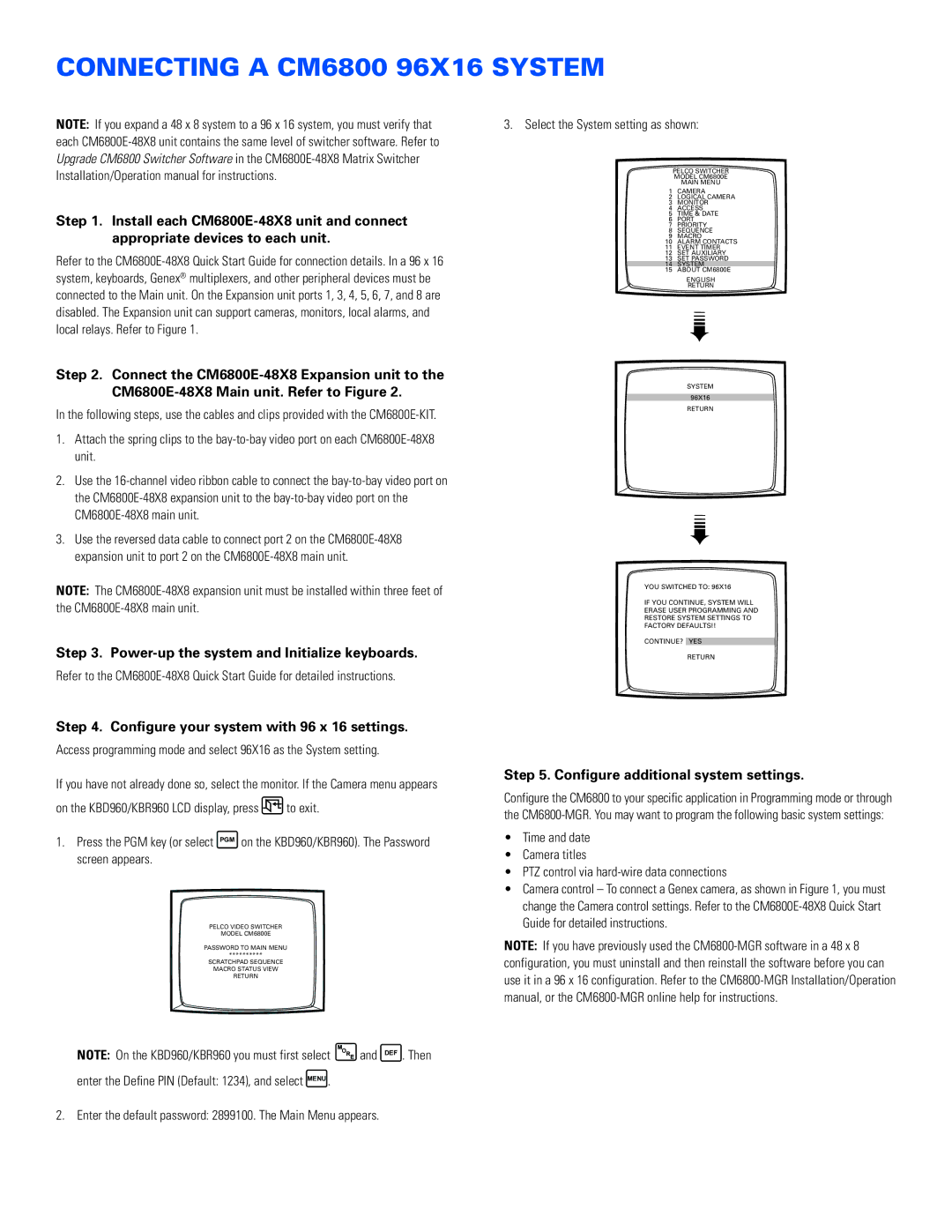
3. Select the System setting as shown:
PELCO SWITCHER
MODEL CM6800E
MAIN MENU
1CAMERA
2LOGICAL CAMERA
3MONITOR
4ACCESS
5TIME & DATE
6PORT
7PRIORITY
8SEQUENCE
9MACRO
10ALARM CONTACTS
11EVENT TIMER
12SET AUXILIARY
13SET PASSWORD
14SYSTEM
15ABOUT CM6800E
ENGLISH
RETURN
➠
SYSTEM
96X16
RETURN
➠
YOU SWITCHED TO: 96X16
IF YOU CONTINUE, SYSTEM WILL
ERASE USER PROGRAMMING AND
RESTORE SYSTEM SETTINGS TO
FACTORY DEFAULTS!!
CONTINUE? YES
RETURN
Step 5. Configure additional system settings.
Configure the CM6800 to your specific application in Programming mode or through the
•Time and date
•Camera titles
•PTZ control via
•Camera control – To connect a Genex camera, as shown in Figure 1, you must change the Camera control settings. Refer to the
NOTE: If you have previously used the
2. Enter the default password: 2899100. The Main Menu appears.