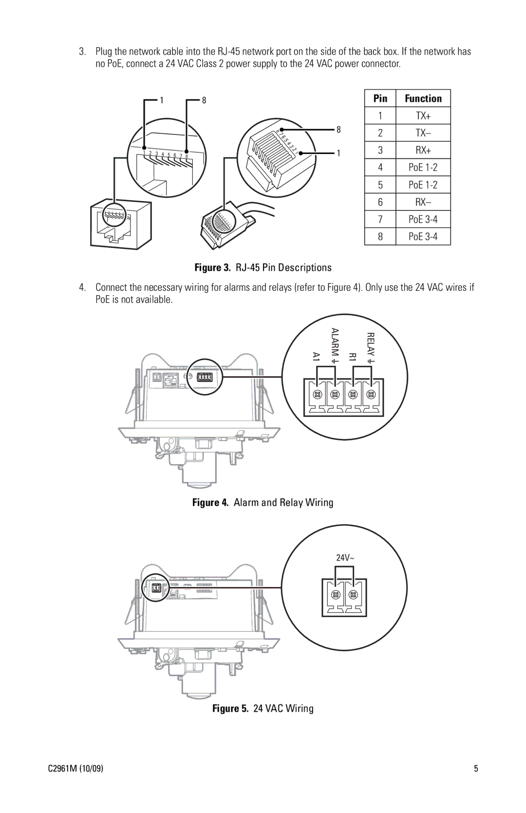
3.Plug the network cable into the
1 |
| 8 |
|
|
|
|
|
|
|
| 8 |
|
|
|
|
|
|
| 7 |
|
|
|
|
|
|
| 6 |
|
|
|
|
|
|
| 5 |
|
|
|
|
|
|
| 4 |
|
|
|
|
|
|
| 3 |
1 | 2 |
|
|
|
|
| 2 |
3 | 4 | 5 | 6 | 7 | 1 | ||
|
| 8 | |||||
|
|
|
|
|
1 | 2 | 3 | 4 | 5 | 6 | 7 | 8 | 8 |
|
|
|
|
|
|
|
| 7 |
|
|
|
|
|
|
|
| 6 |
|
|
|
|
|
|
|
| 5 |
|
|
|
|
|
|
|
| 4 |
|
|
|
|
|
|
|
| 3 |
|
|
|
|
|
|
|
| 2 |
|
|
|
|
|
|
|
| 1 |
| Pin | Function | |
|
|
| |
| 1 | TX+ | |
8 |
|
| |
2 | TX– | ||
| |||
|
|
| |
1 | 3 | RX+ | |
| 4 | PoE | |
|
|
| |
| 5 | PoE | |
|
|
| |
| 6 | RX– | |
|
|
| |
| 7 | PoE | |
|
|
| |
| 8 | PoE | |
|
|
|
Figure 3. RJ-45 Pin Descriptions
4.Connect the necessary wiring for alarms and relays (refer to Figure 4). Only use the 24 VAC wires if PoE is not available.
24V~
RELAY
R1
ALARM
A1
A1 | ALARM | R1 | RELAY | |||||
|
|
|
|
|
|
|
|
|
|
|
|
|
|
|
|
|
|
|
|
|
|
|
|
|
|
|
|
|
|
|
|
|
|
|
|
|
|
|
|
|
|
|
|
|
Figure 4. Alarm and Relay Wiring
24V~
Figure 5. 24 VAC Wiring
C2961M (10/09) | 5 |