Mounting Instructions
WALL MOUNTING
1.Open the lid of the
2.Determine the mounting location for the
3.Use the
4.Prepare the holes for installation.
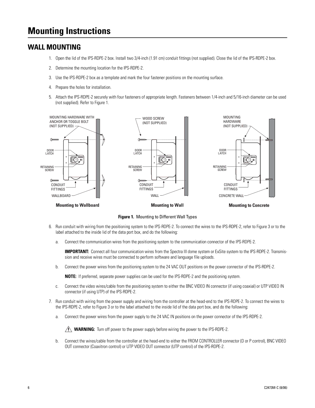
5.Attach the
MOUNTING HARDWARE WITH ANCHOR OR TOGGLE BOLT (NOT SUPPLIED)
DOOR |
LATCH |
RETAINING |
SCREW |
CONDUIT |
FITTINGS |
WALLBOARD |
Mounting to Wallboard
WOOD SCREW (NOT SUPPLIED)
DOOR |
LATCH |
RETAINING |
SCREW |
CONDUIT |
FITTINGS |
WALL |
Mounting to Wall
Figure 1. Mounting to Different Wall Types
MOUNTING
HARDWARE (NOT SUPPLIED)
DOOR |
LATCH |
RETAINING |
SCREW |
CONDUIT |
FITTINGS |
CONCRETE WALL
Mounting to Concrete
6.Run conduit with wiring from the positioning system to the
a.Connect the communication wires from the positioning system to the communication connector of the
IMPORTANT: Connect all four communication wires from the Spectra III dome system or ExSite system to the
b.Connect the power wires from the positioning system to the 24 VAC OUT positions on the power connector of the
c.Connect the video wires/cable from the positioning system to either the BNC VIDEO IN connector (if using coaxial) or UTP VIDEO IN connector (if using UTP) of the
7.Run conduit with wiring from the power supply and wiring from the controller at the
a.Connect the power wires from the power supply to the 24 VAC IN positions on the power connector of the ![]() WARNING: Turn off power to the power supply before wiring the power to the
WARNING: Turn off power to the power supply before wiring the power to the
b.Connect the wires/cable from the controller at the
6 |