Pelco ips-rdpe-2 manual Cable/Wire Requirements and Connector Locations

Models: ips-rdpe-2

1 20
Download 20 pages 48.18 Kb
Page 8
Image 8
Cable/Wire Requirements and Connector Locations

Cable/Wire Requirements and Connector Locations

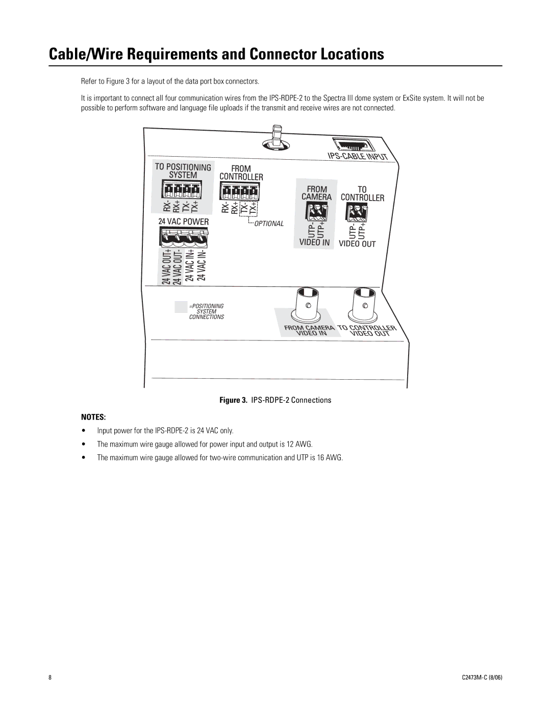
Refer to Figure 3 for a layout of the data port box connectors.

It is important to connect all four communication wires from the IPS-RDPE-2 to the Spectra III dome system or ExSite system. It will not be possible to perform software and language file uploads if the transmit and receive wires are not connected.

OPTIONAL

=POSITIONING

SYSTEM

CONNECTIONS

Figure 3. IPS-RDPE-2 Connections

NOTES:

Input power for the IPS-RDPE-2 is 24 VAC only.

The maximum wire gauge allowed for power input and output is 12 AWG.

The maximum wire gauge allowed for two-wire communication and UTP is 16 AWG.

8

C2473M-C (8/06)

Page 8
Image 8
Pelco ips-rdpe-2 manual Cable/Wire Requirements and Connector Locations