Wiring Diagrams
The
•Coaxitron Controller with Coax Video
•Coaxitron Controller with UTP Video (Passive Receiver Only)
•
–
–Home Run Configuration
–
•
–
–Home Run Configuration
–
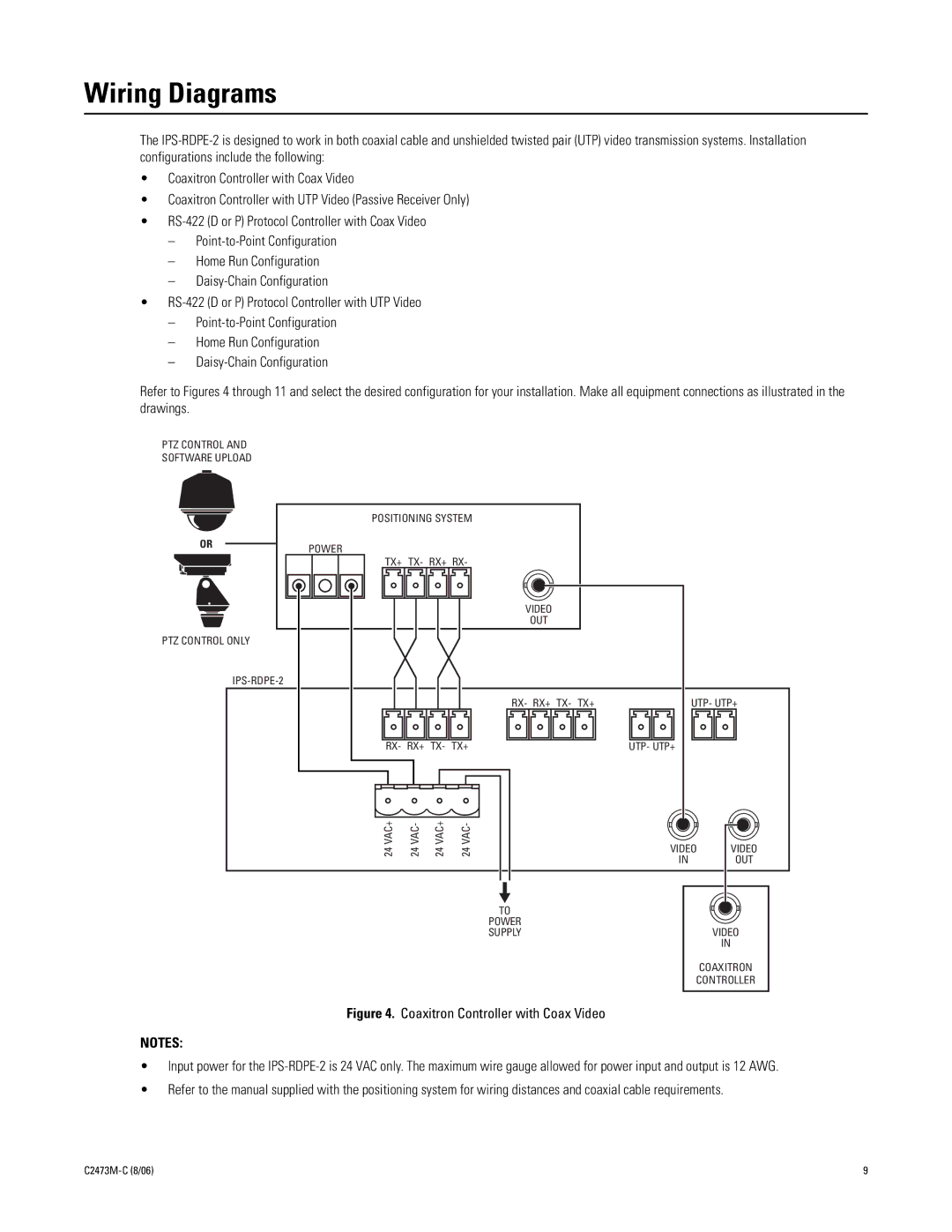
Refer to Figures 4 through 11 and select the desired configuration for your installation. Make all equipment connections as illustrated in the drawings.
PTZ CONTROL AND
SOFTWARE UPLOAD
POSITIONING SYSTEM
OR | POWER |
|
TX+ TX- RX+ RX-
VIDEO
OUT
PTZ CONTROL ONLY
RX- RX+ TX- TX+ | UTP- UTP+ |
RX- RX+ TX- TX+ | UTP- UTP+ |
VAC+ | VAC- | VAC+ | VAC- |
24 | 24 | 24 | 24 |
TO
POWER
SUPPLY
VIDEO | VIDEO |
IN | OUT |
VIDEO
IN
COAXITRON
CONTROLLER
Figure 4. Coaxitron Controller with Coax Video
NOTES:
•Input power for the IPS-RDPE-2 is 24 VAC only. The maximum wire gauge allowed for power input and output is 12 AWG.
•Refer to the manual supplied with the positioning system for wiring distances and coaxial cable requirements.
9 |