3.0 INSTALLATION
Installation instructions for the MR4000 and MRU universal monitor/receiver mounts are divided into two sections. Follow the steps outlined in order to assure a proper
3.1 MR4000 ASSEMBLY
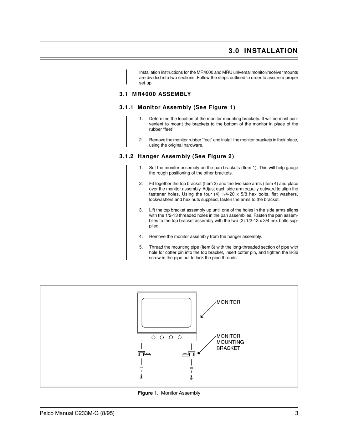
3.1.1Monitor Assembly (See Figure 1)
1.Determine the location of the monitor mounting brackets. It will be most con- venient to mount the brackets to the bottom of the monitor in place of the rubber “feet”.
2.Remove the monitor rubber “feet” and install the monitor brackets in their place, using the original hardware.
3.1.2Hanger Assembly (See Figure 2)
1.Set the monitor assembly on the pan brackets (Item 1). This will help gauge the rough positioning of the other brackets.
2.Fit together the top bracket (Item 3) and the two side arms (Item 4) and place over the monitor assembly. Adjust each side arm equally outward to align the fastener holes. Using the four (4)
3.Lift the top bracket assembly up until one of the holes in the side arms aligns with the
4.Remove the monitor assembly from the hanger assembly.
5.Thread the mounting pipe (Item 6) with the
Figure 1. Monitor Assembly
Pelco Manual | 3 |