PelcoVision™ PV1000 Series
Quick Start Guide
INTRODUCTION
The purpose of this document is to provide the experienced CCTV/electronics user a logical quick start to the PelcoVision™ Phone Line Transmission System. This document will detail the minimum steps necessary to transmit and receive video using the PelcoVision™ system. For detailed installation, programming and operating instructions refer to the PelcoVision™ I/O Manual (C1913M).
Recommendations
PSTN Models: Pelco does not recommend using a PBX phone connection for the PV110 modem due to the possibility of bandwidth limitations or digital voltages. If at all possible, use a true analog, FAX grade phone connection.
ISDN Models: Pelco recommends using the AT&T 5ESS switch type using the Multipoint/Initializing switch version, configured for the Adtrans Express 3000. However, the ISDN switch type and switch is not critical as long as it supports Asynchronous Bonding.
SETTING UP THE RECEIVER TO CALL A TRANSMITTER
This section will provide the minimum details necessary to establish a phone line connection between the PV1016R(N) and the PelcoVision™ demonstration site (PSTN telephone number
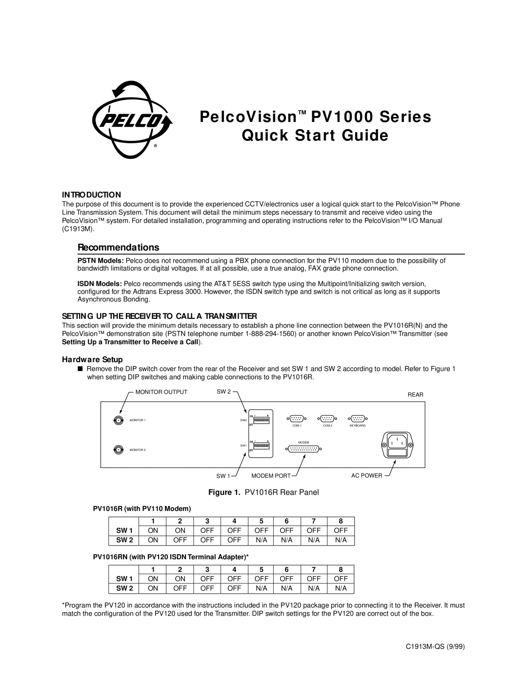
Hardware Setup
■Remove the DIP switch cover from the rear of the Receiver and set SW 1 and SW 2 according to model. Refer to Figure 1 when setting DIP switches and making cable connections to the PV1016R.
MONITOR OUTPUT | SW 2 | REAR |
|
|
MONITOR 1 | SW2 |
SW1
MONITOR 2
COM 1 | COM 2 | KEYBOARD |
MODEM
SW 1 MODEM PORTAC POWER
Figure 1. PV1016R Rear Panel
PV1016R (with PV110 Modem)
|
| 1 | 2 | 3 | 4 |
| 5 | 6 | 7 | 8 |
| SW 1 | ON | ON | OFF | OFF |
| OFF | OFF | OFF | OFF |
|
|
|
|
|
|
|
|
|
|
|
| SW 2 | ON | OFF | OFF | OFF |
| N/A | N/A | N/A | N/A |
|
|
|
|
|
|
|
|
|
|
|
PV1016RN (with PV120 ISDN Terminal Adapter)* |
|
|
|
| ||||||
|
|
|
|
|
|
|
|
|
|
|
|
| 1 | 2 | 3 | 4 |
| 5 | 6 | 7 | 8 |
| SW 1 | ON | ON | OFF | OFF |
| OFF | OFF | OFF | OFF |
| SW 2 | ON | OFF | OFF | OFF |
| N/A | N/A | N/A | N/A |
|
|
|
|
|
|
|
|
|
|
|
*Program the PV120 in accordance with the instructions included in the PV120 package prior to connecting it to the Receiver. It must match the configuration of the PV120 used for the Transmitter. DIP switch settings for the PV120 are correct out of the box.