SETTING UP A TRANSMITTER TO RECEIVE A CALL
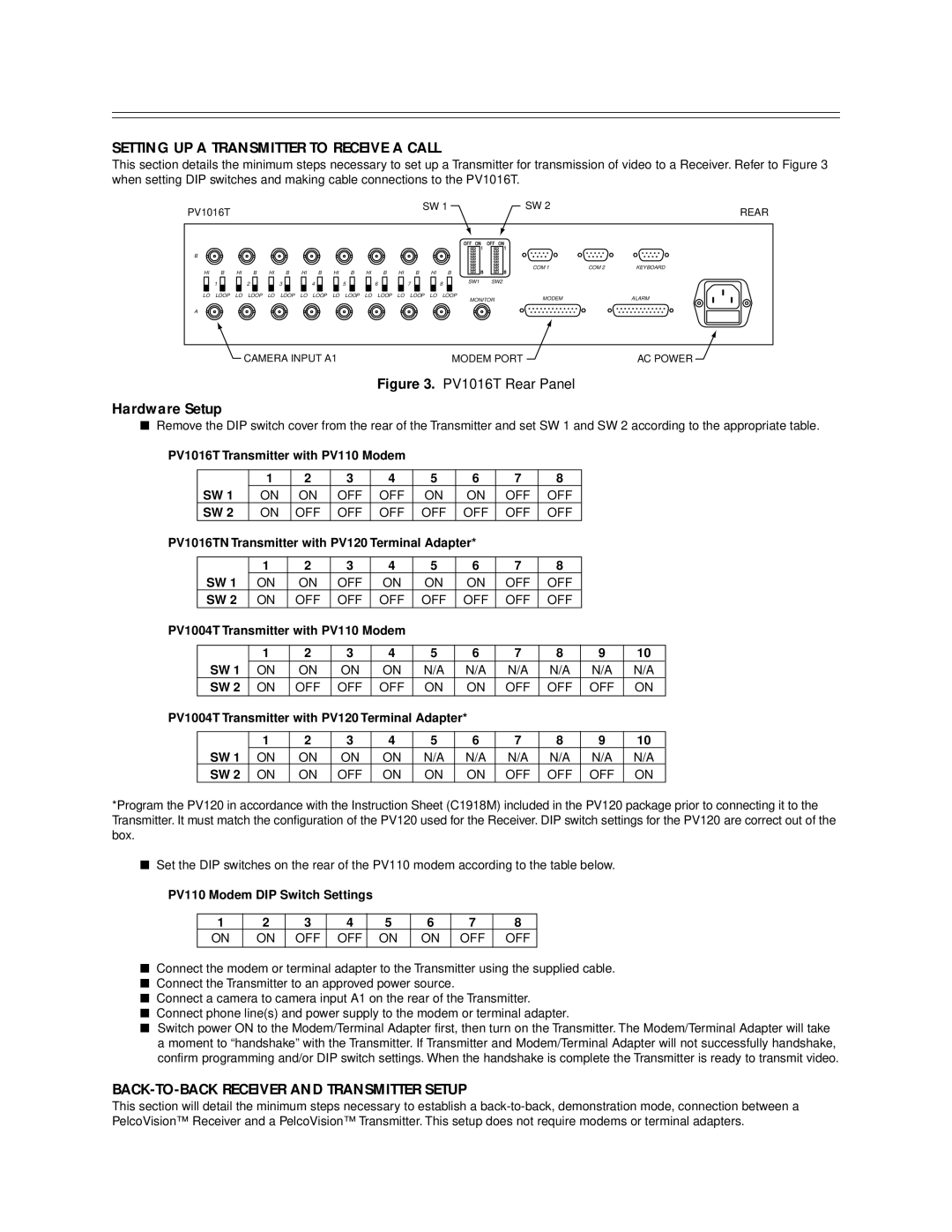
This section details the minimum steps necessary to set up a Transmitter for transmission of video to a Receiver. Refer to Figure 3 when setting DIP switches and making cable connections to the PV1016T.
PV1016T | SW 1 | SW 2 | REAR |
|
|
B
HI |
| B | HI |
| B | HI |
| B | HI |
| B | HI |
| B | HI |
| B | HI |
| B |
| HI |
| B |
|
|
| |||||||||||||
|
| 1 |
|
|
|
| 2 |
|
|
|
| 3 |
|
|
|
| 4 |
|
|
|
| 5 |
|
|
| 6 |
|
|
| 7 |
|
|
|
| 8 |
|
| SW1 |
| SW2 |
|
|
|
|
|
|
|
|
|
|
|
|
|
|
|
|
|
|
|
|
|
|
|
|
|
|
|
|
|
|
| ||||||||||
|
|
|
|
|
|
|
|
|
|
|
|
|
|
|
|
|
|
|
|
|
|
|
|
|
|
|
|
|
|
|
|
|
|
|
|
|
|
|
|
|
LO | LOOP | LO | LOOP | LO | LOOP | LO | LOOP | LO | LOOP | LO | LOOP | LO | LOOP LO | LOOP | MONITOR | |||||||||||||||||||||||||
|
|
|
|
|
|
|
|
|
|
|
|
|
|
|
|
|
|
|
|
|
|
|
|
|
|
|
|
|
|
|
|
|
|
|
|
|
| |||
COM 1 | COM 2 | KEYBOARD |
MODEM |
| ALARM |
A
CAMERA INPUT A1 | MODEM PORT | AC POWER |
Figure 3. PV1016T Rear Panel
Hardware Setup
■Remove the DIP switch cover from the rear of the Transmitter and set SW 1 and SW 2 according to the appropriate table.
PV1016T Transmitter with PV110 Modem |
|
|
|
|
|
| |||||||
|
|
|
|
|
|
|
|
|
|
|
|
|
|
|
|
| 1 |
| 2 | 3 | 4 | 5 | 6 | 7 | 8 |
|
|
| SW 1 | ON | ON | OFF | OFF | ON | ON | OFF | OFF |
|
| ||
| SW 2 | ON | OFF | OFF | OFF | OFF | OFF | OFF | OFF |
|
| ||
PV1016TN Transmitter with PV120 Terminal Adapter* |
|
|
|
| |||||||||
|
|
|
|
|
|
|
|
|
|
|
|
|
|
|
|
| 1 |
| 2 | 3 | 4 | 5 | 6 | 7 | 8 |
|
|
| SW 1 | ON |
| ON | OFF | ON | ON | ON | OFF | OFF |
|
| |
| SW 2 | ON |
| OFF | OFF | OFF | OFF | OFF | OFF | OFF |
|
| |
PV1004T Transmitter with PV110 Modem |
|
|
|
|
|
| |||||||
|
|
|
|
|
|
|
|
|
|
|
|
|
|
|
|
| 1 |
| 2 | 3 | 4 | 5 | 6 | 7 | 8 | 9 | 10 |
| SW 1 | ON | ON | ON | ON | N/A | N/A | N/A | N/A | N/A | N/A | ||
| SW 2 | ON | OFF | OFF | OFF | ON | ON | OFF | OFF | OFF | ON | ||
PV1004T Transmitter with PV120 Terminal Adapter* |
|
|
|
| |||||||||
|
|
|
|
|
|
|
|
|
|
|
|
|
|
|
|
| 1 |
| 2 | 3 | 4 | 5 | 6 | 7 | 8 | 9 | 10 |
| SW 1 | ON | ON | ON | ON | N/A | N/A | N/A | N/A | N/A | N/A | ||
| SW 2 | ON | ON | OFF | ON | ON | ON | OFF | OFF | OFF | ON | ||
*Program the PV120 in accordance with the Instruction Sheet (C1918M) included in the PV120 package prior to connecting it to the Transmitter. It must match the configuration of the PV120 used for the Receiver. DIP switch settings for the PV120 are correct out of the box.
■ Set the DIP switches on the rear of the PV110 modem according to the table below.
PV110 Modem DIP Switch Settings
1 | 2 | 3 | 4 | 5 | 6 | 7 | 8 |
ON | ON | OFF | OFF | ON | ON | OFF | OFF |
|
|
|
|
|
|
|
|
■ Connect the modem or terminal adapter to the Transmitter using the supplied cable. ■ Connect the Transmitter to an approved power source.
■ Connect a camera to camera input A1 on the rear of the Transmitter.
■ Connect phone line(s) and power supply to the modem or terminal adapter.
■ Switch power ON to the Modem/Terminal Adapter first, then turn on the Transmitter. The Modem/Terminal Adapter will take a moment to “handshake” with the Transmitter. If Transmitter and Modem/Terminal Adapter will not successfully handshake, confirm programming and/or DIP switch settings. When the handshake is complete the Transmitter is ready to transmit video.
BACK-TO-BACK RECEIVER AND TRANSMITTER SETUP
This section will detail the minimum steps necessary to establish a