WX8000 specifications
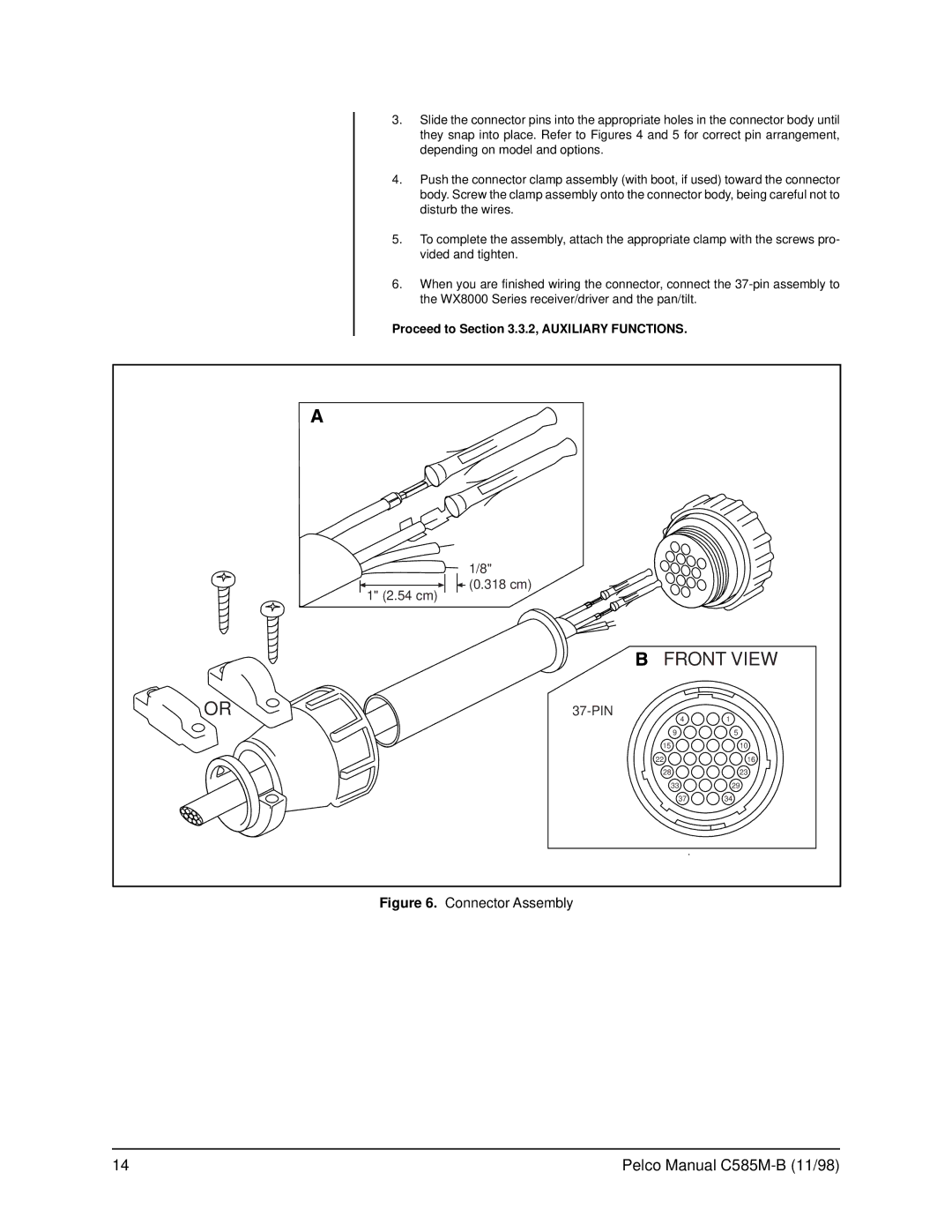
The Pelco WX8000 is a cutting-edge video surveillance system designed for robust, high-performance monitoring in various environments. Ideal for urban settings, industrial complexes, and commercial establishments, the WX8000 is known for its state-of-the-art features that enhance security and operational efficiency.At the heart of the WX8000 is its advanced video analytics capability. This system utilizes intelligent algorithms that can analyze video streams in real-time, enabling users to detect and respond to unusual activities swiftly. Object detection, line crossing, and motion tracking are some of the analytics that can be personalized to meet specific surveillance needs.
One of the standout features of the Pelco WX8000 is its scalability. The system can support multiple cameras and sensors, making it suitable for both small installations and large-scale operations. Users can easily expand their surveillance setup without the need for significant additional infrastructure, ensuring flexibility as security needs change over time.
The WX8000 boasts high-definition video capture capabilities, with options for 4K resolution. This allows for crystal-clear images that maintain detail even in low-light conditions, thanks to the integration of infrared technology. This makes it particularly effective for nighttime surveillance or poorly lit environments.
Furthermore, the system incorporates a user-friendly interface that allows for easy navigation and control. Users can access live feeds, playback recorded footage, and adjust settings with minimal training. This is complemented by multi-device accessibility, letting users monitor their security systems from smartphones, tablets, and PCs.
The Pelco WX8000 is also equipped with enhanced cybersecurity protocols to safeguard against potential threats. With built-in encryption and secure data transmission features, the system ensures that sensitive information remains protected from unauthorized access or tampering.
Another notable characteristic is the system's compatibility with various third-party devices and software. This flexibility allows businesses to integrate existing security solutions into the WX8000 framework, providing a unified approach to monitoring and response.
In summary, the Pelco WX8000 is a sophisticated surveillance solution that combines advanced video analytics, high-definition video capabilities, and robust cybersecurity measures. Its scalability, user-friendly interface, and compatibility with third-party devices make it an excellent choice for enhancing security in diverse environments. As organizations prioritize safety and monitoring, the WX8000 stands out as a reliable and powerful tool in the realm of video surveillance.

