Troubleshooting & Service | 31 |
|
|
SERVICE CHECKS—IGNITION MODULE
Service Checks
Symptom | Cause/Cure | ||
|
|
| |
1. | Dead | A. Miswired | |
|
| B. Transformer bad | |
|
| C. Fuse/Circuit breaker bad | |
|
| D. | Bad control (check LED for steady on) |
|
|
|
|
2. | Thermostat | A. | Miswired |
|
| B. Bad thermostat no voltage at terminal W | |
|
|
|
|
3. | Valve on, no ignitor | A. | Defective ignitor |
|
| B. | Miswired |
|
| C. Bad control (check voltage at ignitor) | |
|
|
|
|
4. | Ignitor on, no valve | A. | Valve coil open |
|
| B. Open valve wire | |
|
| C. Bad control (check voltage between V1 & V2) | |
|
|
|
|
5. | Flame okay during TFI, | A. | Bad ignitor |
| no flame sense (after TFI) | B. | Bad S1 wire |
|
| C. Poor ground at burner | |
|
| D. | Poor flame (check flame current) |
|
|
|
|
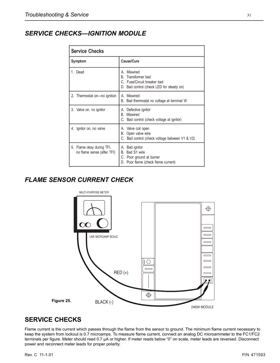
FLAME SENSOR CURRENT CHECK
USE MICROAMP SCALE
RED (+)
Figure 25. | BLACK |
2465H MODULE
SERVICE CHECKS
Flame current is the current which passes through the flame from the sensor to ground. The minimum flame current necessary to keep the system from lockout is 0.7 microamps. To measure flame current, connect an analog DC microammeter to the FC1/FC2 terminals per figure. Meter should read 0.7 µA or higher. If meter reads below “0” on scale, meter leads are reversed. Disconnect power and reconnect meter leads for proper polarity.
Rev. C | P/N 471593 |