SPEED LE RJ45 Back Panel Connectors and Pinout
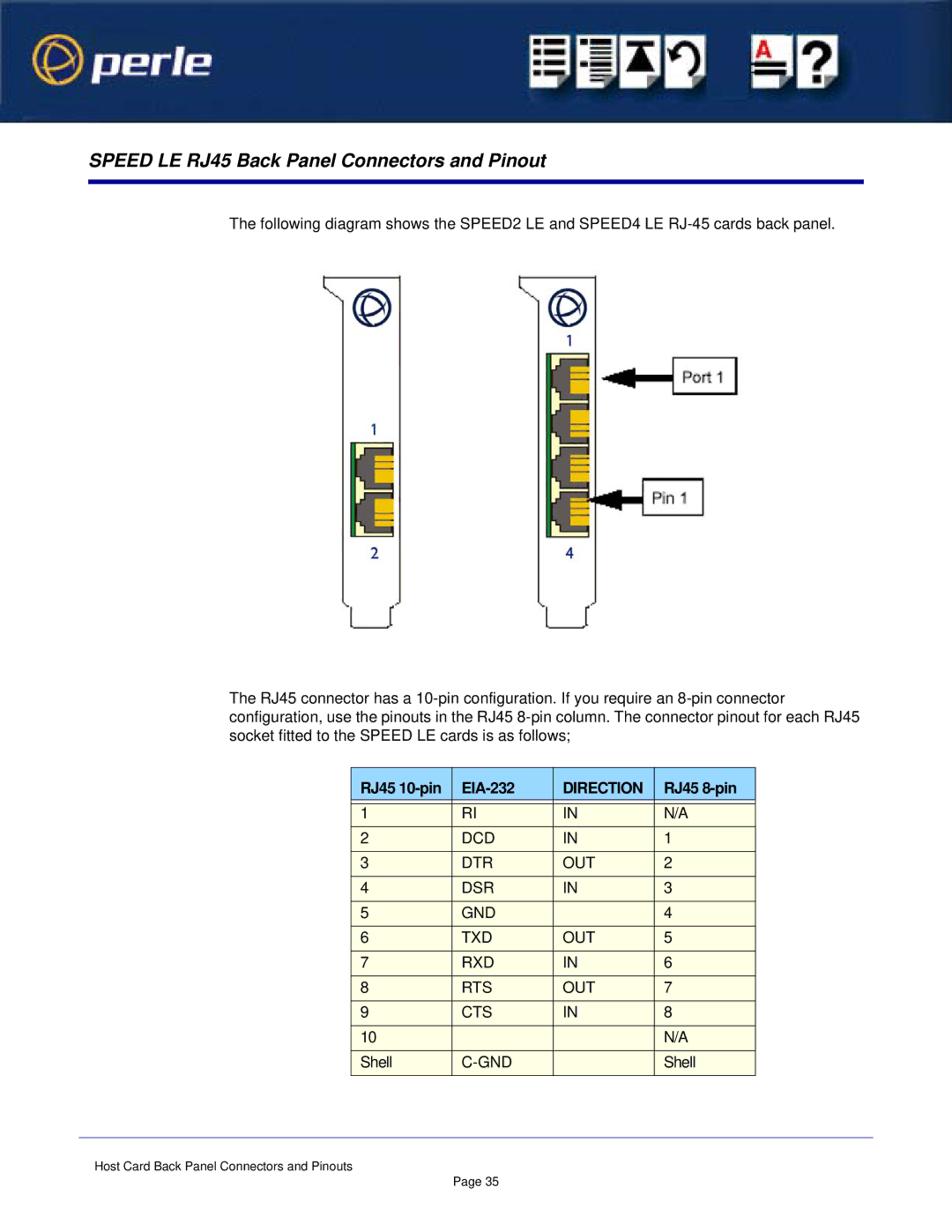
The following diagram shows the SPEED2 LE and SPEED4 LE
The RJ45 connector has a
RJ45 |
| DIRECTION | RJ45 |
|
|
|
|
1 | RI | IN | N/A |
2 | DCD | IN | 1 |
3 | DTR | OUT | 2 |
4 | DSR | IN | 3 |
5 | GND |
| 4 |
6 | TXD | OUT | 5 |
7 | RXD | IN | 6 |
8 | RTS | OUT | 7 |
9 | CTS | IN | 8 |
10 |
|
| N/A |
Shell |
| Shell | |
|
|
|
|
Host Card Back Panel Connectors and Pinouts
Page 35