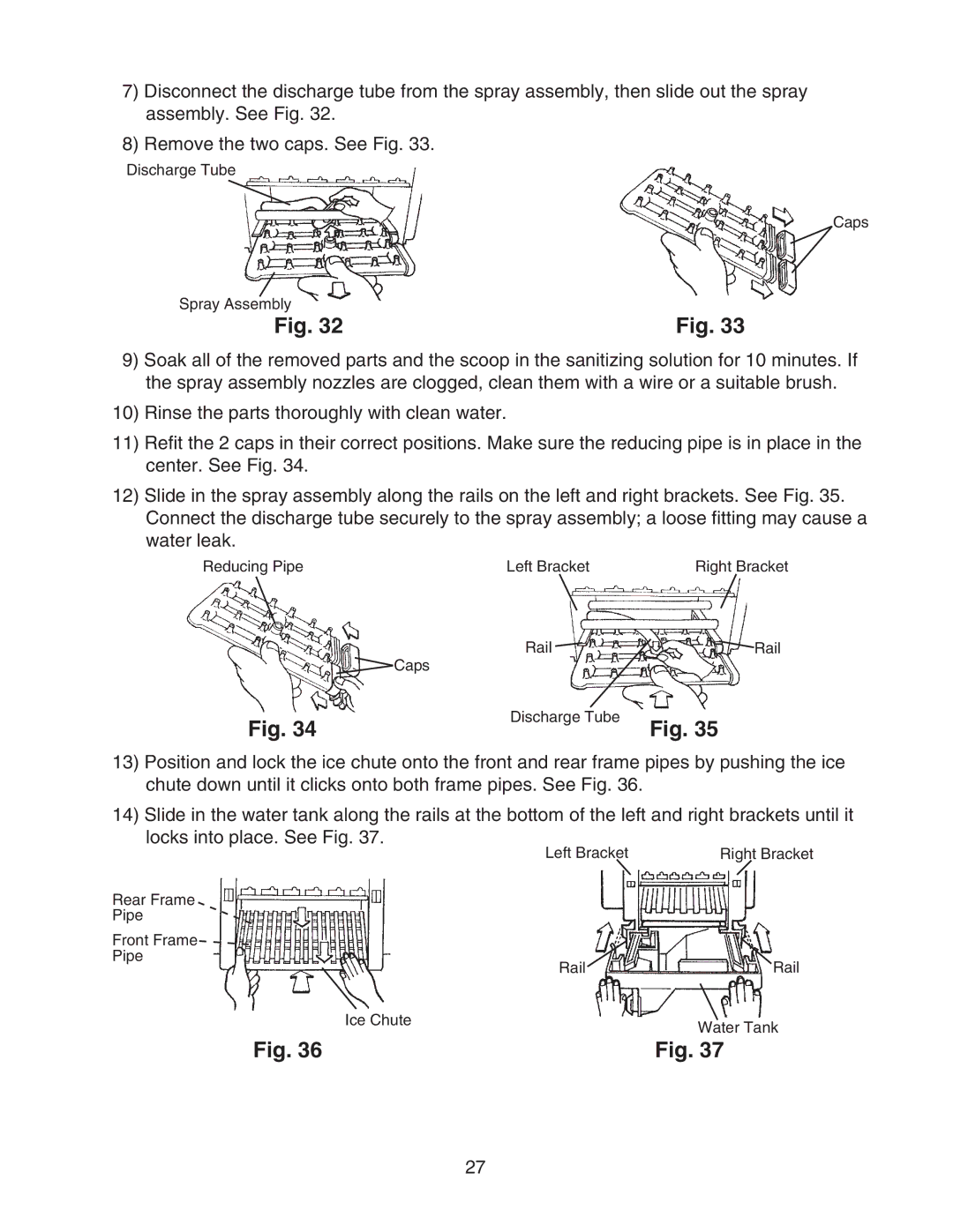
7)Disconnect the discharge tube from the spray assembly, then slide out the spray assembly. See Fig. 32.
8)Remove the two caps. See Fig. 33.
Discharge Tube
Caps
Spray Assembly |
|
Fig. 32 | Fig. 33 |
9)Soak all of the removed parts and the scoop in the sanitizing solution for 10 minutes. If the spray assembly nozzles are clogged, clean them with a wire or a suitable brush.
10)Rinse the parts thoroughly with clean water.
11)Refit the 2 caps in their correct positions. Make sure the reducing pipe is in place in the center. See Fig. 34.
12)Slide in the spray assembly along the rails on the left and right brackets. See Fig. 35. Connect the discharge tube securely to the spray assembly; a loose fitting may cause a water leak.
Reducing Pipe | Left Bracket | Right Bracket |
| Rail | Rail |
| Caps |
|
Fig. 34 | Discharge Tube | Fig. 35 |
|
13)Position and lock the ice chute onto the front and rear frame pipes by pushing the ice chute down until it clicks onto both frame pipes. See Fig. 36.
14)Slide in the water tank along the rails at the bottom of the left and right brackets until it locks into place. See Fig. 37.
| Left Bracket | Right Bracket |
Rear Frame |
|
|
Pipe |
|
|
Front Frame |
|
|
Pipe | Rail | Rail |
| ||
| Ice Chute | Water Tank |
|
| |
| Fig. 36 | Fig. 37 |
27