Product Information
![]() • Dimension (WxHxD)
• Dimension (WxHxD)
![]() • Weight
• Weight
![]() • Tilt / Swivel
• Tilt / Swivel
![]() • Height adjustment range
• Height adjustment range
![]() • Power supply
• Power supply
![]() • Power consumption
• Power consumption
![]() • Temperature
• Temperature
![]() • Relative humidity
• Relative humidity
![]() • System MTBF
• System MTBF
![]() • Cabinet color
• Cabinet color
![]() • Altitude
• Altitude
-storage/shipment
-operating
![]()
![]() 461 x 421 x 215.3 mm (incl. Pedestal) (in lowest position)
461 x 421 x 215.3 mm (incl. Pedestal) (in lowest position)
![]()
![]() 8.9 Kg
8.9 Kg
![]()
![]()
![]()
![]() 130 mm
130 mm
![]()
![]() 100— 240 VAC, 60 - 50 Hz
100— 240 VAC, 60 - 50 Hz
![]()
![]() 50 W* (typ.)
50 W* (typ.)
5° C to 35° C (operating)
![]()
![]() 20% to 80%
20% to 80%
![]()
![]() 50K hrs (excluding CCFL 40K hrs)
50K hrs (excluding CCFL 40K hrs) ![]()
![]() Black/Silver
Black/Silver
0 - 40,000 feet (12,192m)
0 - 12,000 feet (3657.6m)
*This data is subject to change without notice.
*Resolution 1600 x 1200, standard size, contrast max., brightness 50%, 6500° K, full white pattern.
RETURN TO TOP OF THE PAGE
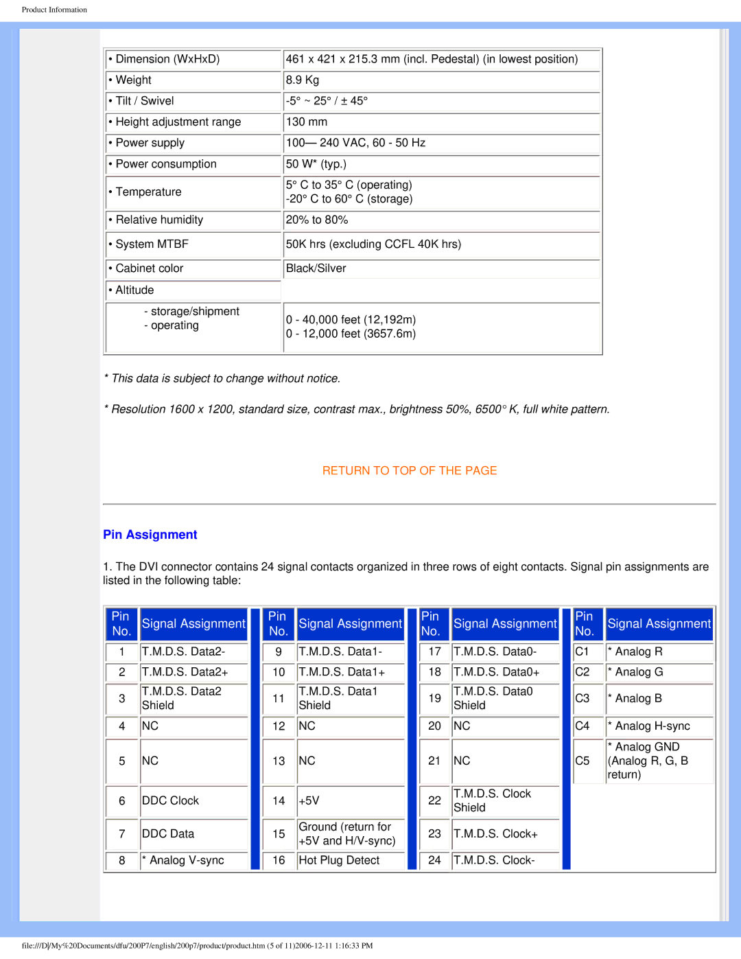
Pin Assignment
1.The DVI connector contains 24 signal contacts organized in three rows of eight contacts. Signal pin assignments are listed in the following table:
|
|
|
|
|
|
|
|
|
|
|
|
|
|
|
|
|
|
|
|
|
|
|
| Pin |
| Signal Assignment |
|
| Pin |
| Signal Assignment |
| Pin |
| Signal Assignment |
| Pin |
| Signal Assignment |
| |||||
| No. |
|
|
|
| No. |
|
|
|
| No. |
|
|
|
| No. |
|
| ||||
1 |
| T.M.D.S. Data2- |
|
| 9 |
| T.M.D.S. Data1- |
|
| 17 |
| T.M.D.S. Data0- |
|
|
| C1 |
| * Analog R | ||||
2 |
| T.M.D.S. Data2+ |
|
| 10 |
| T.M.D.S. Data1+ |
|
| 18 |
| T.M.D.S. Data0+ |
|
|
| C2 |
| * Analog G | ||||
3 |
| T.M.D.S. Data2 |
|
| 11 |
| T.M.D.S. Data1 |
|
| 19 |
| T.M.D.S. Data0 |
|
|
| C3 |
| * Analog B | ||||
| Shield |
|
|
| Shield |
|
|
| Shield |
|
|
|
| |||||||||
4 |
| NC |
|
| 12 |
| NC |
|
| 20 |
| NC |
|
|
| C4 |
| * Analog | ||||
|
|
|
|
|
|
|
|
|
|
|
|
|
|
|
|
|
|
|
|
| * Analog GND | |
5 |
| NC |
|
| 13 |
| NC |
|
| 21 |
| NC |
|
|
| C5 |
| (Analog R, G, B | ||||
|
|
|
|
|
|
|
|
|
|
|
|
|
|
|
|
|
|
|
|
| return) | |
6 |
| DDC Clock |
|
| 14 |
| +5V |
|
| 22 |
| T.M.D.S. Clock |
|
|
|
|
|
|
| |||
|
|
|
|
|
|
| Shield |
|
|
|
|
|
|
| ||||||||
7 |
| DDC Data |
|
| 15 |
| Ground (return for |
|
| 23 |
| T.M.D.S. Clock+ |
|
|
|
|
|
|
| |||
|
|
|
| +5V and |
|
|
|
|
|
|
|
|
|
| ||||||||
|
|
|
|
|
|
|
|
|
|
|
|
|
|
|
|
|
|
|
|
|
| |
8 |
| * Analog |
|
| 16 |
| Hot Plug Detect |
|
| 24 |
| T.M.D.S. Clock- |
|
|
|
|
|
|
| |||
|
|
|
|
|
|
|
|
|
|
|
|
|
|
|
|
|
|
|
|
|
|
|
file:///D/My%20Documents/dfu/200P7/english/200p7/product/product.htm (5 of