Philips Professional and Business Solutions
Table of Contents
Important safety instructions
Read Before Operating Equipment
Know these safety symbols
U T I O N
Safety information and useful tips
Pull the power lead by the plug do not pull by the wire
Before calling service
Symptoms Suggested steps
Configuring the control options on
Remote
Antenna connection
Switching on the TV
Mains connection
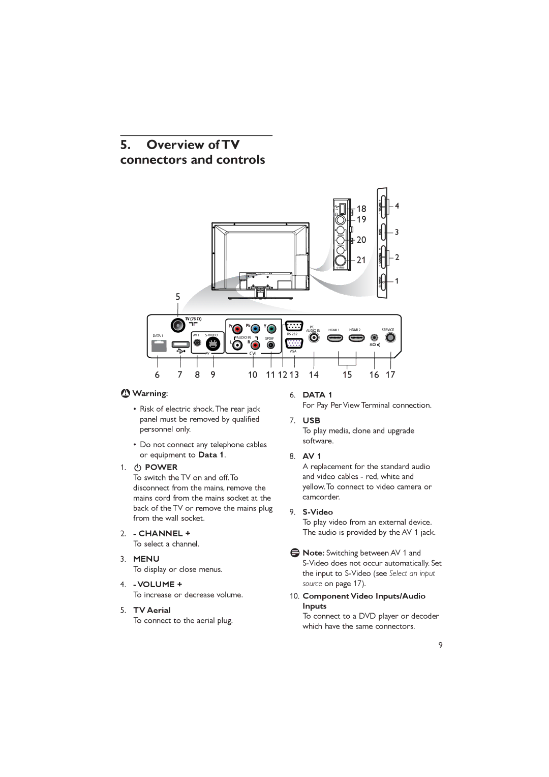
Overview of TV Connectors and controls
Menu
Spdif
RC2573GR
Optional remote controls
RC2888/01
Description of guest remote control
Setup
Overview of TV menus
Slide the button to the Setup location
Accessing the setup menu
Accessing TV Setup Menu using the Remote Control RC2573GR
To scroll through the menu
Selecting the communication source
Installation
Selecting the language
Serial Xpress Multi RC Smart RC OFF
Channel Install
Changing the settings of a channel
Press Æ to enter the Channel Install menu
Select a Channel
TUNER,AV, SVIDEO, CVI, VGA, HDMI1, HDMI2, CARD-CVBS
Side Svideo
Naming a channel
Press 0 9 to key in the channel number 1 to
Selecting your Preferred Ring
Selecting the Mute Source
Auto Install TV
Selecting cable or antenna mode
Select YES to use Cable mode and no to use Antenna mode
Cable Tuning YES
Press Æ to enter the Digital Setup mode
Setting options for digital channels
To enable Current RING, select from RING1 to RING4
Selecting a virtual or physical channel
Press Æ to enter the Audio mode
Setting up the Vchip / Digital Rating and Factory CH Reset
Press Æ to enter the Channel Setup mode
Selecting the Digital Audio language
Select on option to enable Emergency Alert
Activating the Emergency Alert
Specifying the configuration when switching on TV
Press Î ï to select the item you want to configure
Press Î or ï to select the item you want to configure
Channel Display
Fullscreen
Sound
Press ï and select Security
Press ï to select Remote Control Lock
Press Æ to enter the Security menu
Control
Password
Press ï to select Decryption
Press Æ to enter the Decryption Control menu
Press Æ to enter the Vtrack menu
Using V-Track to watermark
Time Setting option allows you to manually enter the time
Configuring the control options
Control ESP
Digit Timeout
Control ESP OFF
Digit Entry YES
PIC FMT Menu Item YES
Configuring the features options and settings
Press Æ to enter the Features menu
Channel Guide YES
Select and configure the settings and options for
Select Smart Sound to listen to different Smart Sound modes
Software downloading and cloning
Select SW Download
Standby Firmware only download
USB Source
ALL Clone Data SSB NVM
Iboard NVM
USB device
RF Source
CC / V-CHIP
ALL SSB NVM
SW Download Source
CC / V Chip Save CC
OFF and on Mute
Digital CC Mode option
Analog CC Mode option, it
V-CHIP Menu Item option
Configure Ambilight
10.10Change Ambilight settings
COLOR, RELAXED, MODERATE, Dynamic
LOW, MED and High
Custom
Press to exit
Appendix a
Support for multiple remote controls
Programming the Multi Remote Controls function
Communication
Definitions, acronyms and abbreviations
Cvbs
OSD
STB
Philips F1rst Choice Limited Warranty
USA limited warranty
Philips’ Commercial Television
What WE will do to Correct PROBLEMS?
Page
Just a phone call away
Environmental care
Cleaning and care
Do not rub with dust clothes containing chemical treatment
Index
Page
Page
Kensington Security Slot
Dolby Digital
If present