Display User Manual
3D Solutions
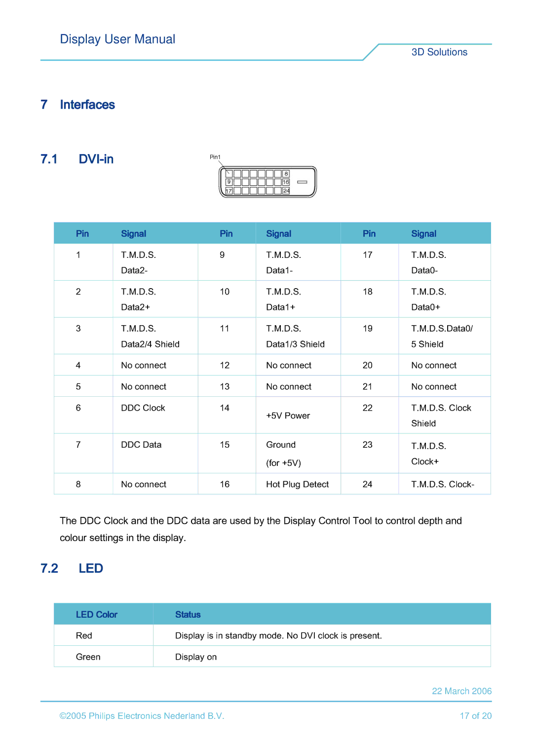
7 Interfaces
7.1
|
|
|
|
|
|
|
|
|
|
|
|
|
|
|
|
|
|
|
|
|
|
|
|
|
|
|
|
|
|
|
|
|
|
|
|
|
|
| |||
| Pin |
|
| Signal |
|
| Pin |
|
| Signal |
|
| Pin |
|
| Signal |
| |||
| 1 |
|
| T.M. | .S. |
|
| 9 |
|
| T.M. | .S. |
|
| 17 |
|
| T.M. | .S. |
|
|
|
|
|
| - |
|
|
|
|
|
| - |
|
|
|
|
|
| - |
|
| 2 |
|
| T.M. | .S. |
|
| 10 |
|
| T.M. | .S. |
|
| 18 |
|
| T.M. | .S. |
|
| 3 |
|
| Data2+ |
|
| 11 |
|
| Data1+ |
|
| 19 |
|
| Data0+T.M. . .Data0/ |
| |||
|
|
| T.M. .S. |
|
|
|
| T.M. .S. |
|
|
|
|
| |||||||
| 4 |
|
| Data2/4 Shield |
| 2 |
|
| Data1/3 Shield |
| 0 |
|
| 5 Shield |
| |||||
| 5 |
|
| No connect |
|
| 3 |
|
| No connect |
|
| 1 |
|
| No connect |
| |||
|
|
|
|
|
|
|
|
|
|
|
|
|
|
|
| |||||
| 6 |
|
| DDC Clock | 14 |
|
| +5V Power | 22 |
|
| T.M.D.S. Clock |
| |||||||
| 7 |
|
| DDC Data | 15 |
|
| 23 |
|
| Shield |
| ||||||||
|
|
|
|
| Ground |
|
| T.M.D.S. |
| |||||||||||
7.2 Thecolour8LEDDDCsettingsClockNoinandconnectthethedisplayDDC. data are16used by (forHotthe +5V)PlugDisplayDetectControl Tool24 to controlClock+T.depthM.D.S.andClock-
LED Color | Status | is in standby mode. No DVI clock is present. |
|
Red |
| 17 of 20 | |
©2005GreenPhilips Electronics NederlandDisplay onB.V. | |||
|
|
| 22 March 2006 |